
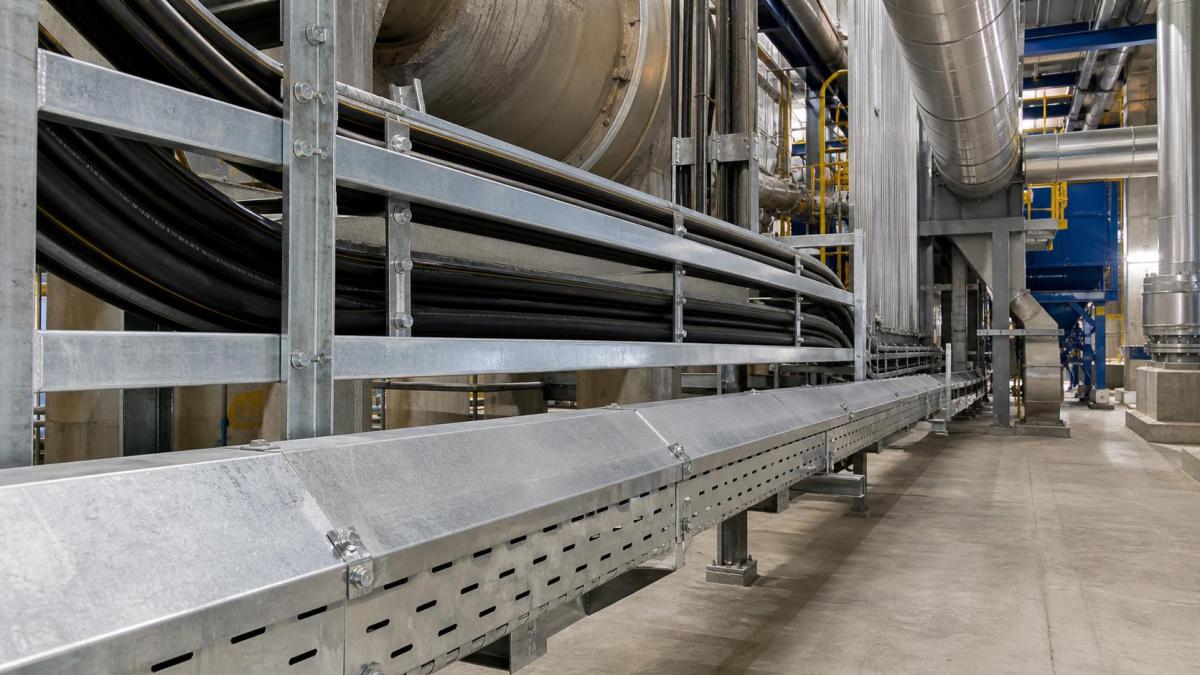
Waste-to-energy plants combine waste reception, combustion, boiler systems, flue-gas treatment, turbine generation, water treatment, and outdoor utilities within one facility. Cable tray routes can pass through dust, moisture, corrosive residues, temperature changes, vibration, and restricted maintenance zones. A single cable tray specification for the entire plant rarely reflects these differences. EPC contractors should divide the project into exposure zones and define the cable support package for each route.
Divide the Plant Into Cable Management Zones
The waste bunker and handling area may contain dust, moisture, impact risk, and aggressive airborne contaminants. Boiler and ash-handling areas can expose equipment to heat and fine particles. Flue-gas treatment sections may include chemicals and condensate, while turbine halls and electrical rooms are generally cleaner but carry dense power and control services.
Route schedules should identify indoor or outdoor location, ambient and radiant temperature, moisture, washdown, chemical exposure, dust, vibration, fire requirements, and access conditions. This zoning allows buyers to use economical systems in controlled rooms while specifying greater protection where the environment demands it.
Match Cable Tray Type to the Cable Group
Main power feeders for pumps, fans, conveyors, boiler auxiliaries, turbine systems, and balance-of-plant equipment can create heavy routes. Cable ladder supports large power cables while allowing ventilation and cable cleating. Perforated cable tray provides continuous support for smaller power, control, and instrumentation cables. Cable trunking can enclose lightweight circuits where falling dust or contact must be limited.
- Cable ladder: for heavy power feeders, large motor cables, vertical risers, and routes requiring cable cleats.
- Perforated cable tray: for control, instrumentation, and smaller power circuits needing continuous support.
- Wire mesh cable tray: for flexible communication and low-voltage routing in clean or controlled areas.
- Cable trunking: for enclosed protection in dusty service spaces and local equipment connections.
Power, variable-frequency-drive, instrumentation, fire alarm, and data cables may need separation. The electrical specification should define separate trays, spacing, or divider plates before tray width and route elevation are frozen.
Heat and Dust Need Different Responses
A steel tray remains mechanically strong at many industrial temperatures, but cable temperature is the governing issue for current capacity and insulation life. Routes near boilers, ducts, ash conveyors, and hot piping should maintain the project clearance or use an engineered heat shield. A heavier tray does not compensate for an overheated cable.
Dust and falling particles may justify covers, but solid covers reduce ventilation and can retain deposits if the route is not accessible for cleaning. Peaked covers can help shed material. Ventilated covers may suit areas where airflow remains important. Cover type should be defined by zone, with matching covers and clamps for fittings.
Selection Table by Plant Zone
| Plant Zone | Typical Cable Tray Requirement | RFQ Focus |
|---|---|---|
| Waste receiving and ash handling | Heavy-duty galvanized ladder tray or covered perforated tray | Check dust, vibration, impact risk, supports, covers, and cleaning access. |
| Boiler and flue-gas treatment areas | Hot-dip galvanized or stainless steel tray depending on heat and corrosive exposure | Confirm distance from hot equipment, chemical vapors, expansion joints, and compatible fasteners. |
| Electrical rooms and control buildings | Perforated cable tray, cable ladder, or cable trunking | Coordinate cable segregation, panel entry details, bend radius, and future spare capacity. |
| Outdoor utility corridors | Hot-dip galvanized ladder tray with route-specific covers | Review wind exposure, rain, UV, cover clamps, bonding, and packing by installation area. |
For export orders, route-based packing is particularly useful on waste-to-energy projects because tray sections may be installed in different buildings at different construction stages. Marking bundles by boiler area, turbine hall, flue-gas treatment, ash handling, and electrical room helps the site team locate fittings and support hardware without sorting the full shipment on site.
Material and Finish Selection
Pre-galvanized steel may be suitable for dry electrical rooms and controlled indoor areas. Hot-dip galvanized cable tray is commonly considered for humid process zones, outdoor racks, and utility areas where a heavier zinc coating is required. The RFQ should state the applicable coating standard and whether fabrication occurs before galvanizing.
Stainless steel may be considered near chemical dosing, flue-gas cleaning equipment, condensate, wastewater systems, or repeated washdown. Grade selection should follow the actual chemicals, chloride level, temperature, and cleaning practice. Aluminum can reduce installed weight in selected areas, but load, fire, galvanic compatibility, and project standards require review.
Powder coating can add color identification or supplementary protection. Buyers should state the base material, preparation, color, coating thickness if required, and repair method. An undefined painted finish is difficult to compare across supplier quotations.
Supports, Vibration, and Maintenance Access
Large fans, pumps, conveyors, crushers, and ash-handling equipment can transmit vibration. Supports should connect to suitable structural steel or concrete, with verified brackets, strut channels, threaded rods, beam clamps, and anchors. Light handrails, removable platforms, and cladding members should not be used as supports unless specifically engineered.
The design load should include tray self-weight, cables, covers, dividers, cleats, and future allowance. Support spacing must follow verified product load data. Additional supports may be required at bends, tees, reducers, risers, and heavy cable drops.
Cable routes should remain clear of access doors, equipment withdrawal paths, lifting zones, inspection platforms, and refractory or duct maintenance areas. A route that blocks boiler cleaning or fan removal can create expensive modifications during commissioning or shutdown.
Fittings and Accessories Buyers Should Include
- Horizontal and vertical bends with suitable cable radii
- Tees, crosses, reducers, risers, drop-outs, and end plates
- Splice plates, complete fastener sets, and expansion connectors
- Straight and fitting covers with appropriate clamps
- Divider plates and cable cleats
- Cantilever arms, trapeze supports, strut channel, beam clamps, and anchors
- Grounding lugs and bonding jumpers, especially across movement joints
Long outdoor routes may need expansion provisions. The design should coordinate fixed points, guide supports, expansion connectors, cable slack, and bonding continuity. Supplying an expansion connector without the related movement detail does not create a complete installation.
Installation and Inspection Priorities
Field cuts and drilled holes should receive the specified corrosion-repair treatment. Installers should maintain support spacing through route changes and use the correct splice hardware. Covers and clamps need inspection in vibration and outdoor wind zones. Drainage and cleaning access should be maintained where moisture or residue can collect.
Grounding and bonding connections should remain accessible until inspected and tested. Cable cleats on vertical or high-fault power routes should follow the electrical design. Route labels, packing references, and area codes help construction teams install the correct material in each exposure zone.
RFQ Checklist for Waste-to-Energy Projects
- Plant area and exposure: dust, heat, moisture, chemical, washdown, outdoor, or vibration
- Tray type, width, side height, length, thickness, and rung spacing
- Material grade, surface finish, and applicable coating standard
- Cable group, cable load, future allowance, and segregation requirements
- Support spacing, substrate, bracket arrangement, and anchor conditions
- Fitting schedule with angles, radii, branch sizes, and equipment interfaces
- Cover type, clamps, dividers, cleats, splice plates, and bonding accessories
- Temperature criteria, expansion requirements, documents, packing codes, and delivery sequence
Work With Hongfeng Electric
Hongfeng Electric can review cable tray schedules, environmental zones, load data, fitting quantities, covers, and support accessories for waste-to-energy projects. To request a quotation, send the route drawings or BOQ, cable data, material and finish requirements, support spacing, fitting list, area codes, and delivery destination. HF Cable Tray can then define the supply scope and identify missing interface items before production.
Navigation
Send Us A Message
Get in touch with us
Phone