
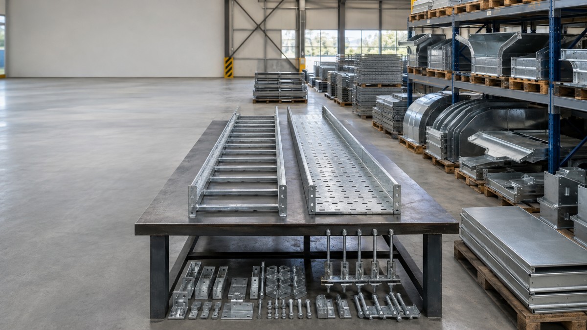
Cable tray in an operating plant is easy to overlook because it is passive equipment. It may carry cables for decades while production changes, new circuits are added, coatings age, supports are altered, and nearby piping or structures are modified. A tray route can still look generally serviceable while local corrosion, loose joints, overloaded sections, damaged supports, or blocked access create growing maintenance risk.
A useful condition assessment does more than list defects. It determines whether each section can remain in service, needs a controlled repair, requires engineering review, or should be replaced during a planned shutdown. That decision must consider the tray, supports, fittings, hardware, bonding provisions, cable condition, loading, environment, and consequences of failure as one system. The following framework helps plant owners, maintenance teams, and procurement buyers organize that work without treating every stain as an emergency or every severe defect as a cosmetic issue.
When a Cable Tray Condition Assessment Is Needed
Routine visual checks may be part of normal plant maintenance, but a focused assessment is especially valuable before an expansion, major cable addition, electrical reliability program, corrosion campaign, shutdown, or change of service. It is also appropriate after impact damage, fire or high-temperature exposure, flooding, chemical release, structural movement, severe weather, or repeated reports of loose covers and supports.
The survey scope should define route limits, operating constraints, required access, documentation format, and who is qualified to evaluate electrical and structural conditions. Existing drawings may not match the installed system, so the team should establish a route register using area names, elevations, photographs, and unique location identifiers. This allows defects to be tracked and repair materials to be ordered against real field conditions.
Inspection near energized cables, moving machinery, hot surfaces, chemicals, or elevated work areas requires the plant's approved safety procedures. Visual evidence should be collected from a safe position. Covers, cables, bonding connections, or supports should not be disturbed unless isolation, access, and authorization requirements have been satisfied.
Inspect the Complete Support System
Tray Rails, Rungs, Bottoms, and Fittings
Check side rails for bending, buckling, cracks, cut-outs, impact marks, severe corrosion, and unapproved field modifications. Ladder rungs should remain securely attached and reasonably straight. Perforated tray bottoms should not show tearing around holes or broad areas of deformation. At elbows, tees, reducers, and risers, look for distortion caused by cable pulling, inadequate support, or congested cable exits.
Splices, Fasteners, and Covers
Splice plates should match the tray profile and sit correctly against the rails. Missing, loose, heavily corroded, or visibly different fasteners should be recorded. Covers require their own review because wind, vibration, poor clamps, and repeated removal can damage them. A loose cover can be a hazard even when the tray body is sound. Check whether covers trap water or debris and whether ventilation remains consistent with the cable design.
Supports and Structural Connections
A tray is only as reliable as its supports. Inspect cantilever brackets, trapeze members, threaded rods, posts, hold-down clamps, anchors, welds, and connections to the main structure. Look for missing supports, excessive spacing, rotation, settlement, vibration wear, bent rods, loose anchors, corrosion at water traps, and unauthorized loads. Pipework, temporary cables, tools, and stored materials should not be supported from the tray unless the system was specifically engineered for them.
Separate Cosmetic Aging from Active Deterioration
Surface appearance alone does not establish remaining capacity. Galvanized steel can develop normal weathering, staining, or localized discoloration without immediate structural loss. Conversely, corrosion hidden beneath debris, at overlapping plates, around fasteners, or where dissimilar metals contact can progress while broad surfaces still look acceptable. The assessment should record the location, extent, depth indication, probable cause, and whether deterioration is active.
Common corrosion drivers include coastal salts, chemical vapors, washdown water, condensation, leaking pipes, damaged coatings, poor drainage, and material mismatch. A successful repair addresses the cause as well as the visible metal. Simply coating over contamination or active corrosion can hide the condition without restoring performance. Where section loss, cracking, attachment failure, or uncertain structural capacity is present, a qualified engineer should determine whether repair is acceptable.
Material identification matters when replacement parts are ordered. Tray, fittings, splice hardware, supports, and fasteners may not all be the same material. New stainless steel or galvanized components should not be mixed into an existing system without reviewing compatibility, electrical bonding, and the actual environment.
Classify Findings for Action
A simple action classification helps maintenance, engineering, and procurement teams work from the same priorities. The categories below are a planning framework, not a substitute for plant procedures or engineering judgment.
| Action Class | Typical Finding | Recommended Response |
|---|---|---|
| Continue and monitor | Light weathering, stable staining, intact members, secure supports, no visible deformation | Record baseline photographs, remove permitted debris, correct moisture source where possible, and reinspect at the plant-defined interval |
| Routine repair | Isolated coating damage, loose cover clamp, missing noncritical hardware, minor accessible defect | Use approved materials and procedures, verify compatible parts, document completion, and check the surrounding route for the same cause |
| Engineering review | Uncertain loading, broad corrosion, bent rail, altered support, vibration damage, material mismatch, questionable bonding | Restrict additional loading, gather dimensions and cable data, obtain qualified assessment, and define repair or replacement scope |
| Priority replacement | Failed support, severe section loss, cracked component, unstable cover, major impact damage, progressive deformation | Apply plant risk controls, protect the area, engineer temporary measures if needed, and schedule controlled replacement with cable protection |
Check Loading, Access, and Electrical Continuity
Many older routes carry more cables than shown on original drawings. The survey should record approximate fill, large cable groups, unsupported exits, cable ties or cleats, and evidence of cable movement. Visible tray deflection may indicate a loading or support issue, but the absence of deflection does not confirm spare capacity. Proposed additions should be checked against the actual tray configuration, support spacing, fitting arrangement, and available load documentation.
Access is a condition issue as well as an installation issue. Congested platforms, later-installed piping, insulation, ducts, or structural steel can prevent cover removal and repair. Cables that cross sharp edges or leave the tray without suitable support should be identified. Maintenance plans should preserve safe access to splices, bends, branches, and bonding points rather than replacing components in the same inaccessible arrangement.
Grounding and bonding provisions should be checked by qualified personnel against the approved electrical design. Missing jumpers, corroded connections, painted contact surfaces, unapproved material transitions, or loose joints may require testing and corrective work. Visual inspection alone cannot prove electrical continuity, and tray hardware should not be disturbed around energized systems without authorization.
Plan Repairs and Replacement Around Plant Operations
Replacement can be more difficult than new installation because existing cables must remain supported and protected. The plan should identify isolation needs, temporary cable support, lifting and access constraints, cutover sequence, fire and gas implications, and protection from hot work or metal debris. A short damaged section may still require several adjacent sections to be opened so loads can be transferred safely.
Field dimensions should be verified before fabrication. Older tray profiles may no longer match current products, and nominal widths do not guarantee compatible splice plates. Transition sections, custom supports, adjustable connections, or full route segments may be required. For shutdown work, preassembled kits organized by location can reduce time spent searching for fittings and fasteners.
- Create a route register with location codes, photographs, tray dimensions, material, and defect class.
- Identify the cause of damage or corrosion before selecting the repair method.
- Verify existing profiles, splice geometry, and support details in the field.
- Separate immediate risk controls from permanent engineered repairs.
- Package replacement parts by route and include all matching hardware and coating-repair materials.
- Update drawings and maintenance records after the work is completed.
Final Buying Advice
Condition assessment should turn field observations into clear actions. Continue monitoring stable sections, repair isolated defects with approved methods, obtain engineering review where capacity or electrical performance is uncertain, and replace components that no longer provide reliable support. The most economical program usually combines these actions instead of replacing every aged route or postponing all work until failure.
For replacement or retrofit enquiries, HONGFENG / Cable Tray Pro can review field dimensions, tray profiles, material conditions, fitting requirements, and route-based packing needs. Supplying photographs and measured connection details helps develop compatible replacement sections and a more practical maintenance package.
Navigation
Send Us A Message
Get in touch with us
Phone