
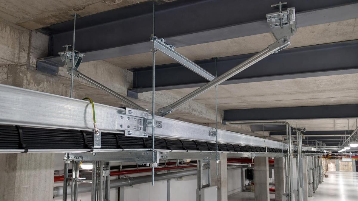
Cable tray systems are often treated as nonstructural electrical work, but in seismic regions their supports and restraints become part of the building's earthquake performance. A tray may have adequate vertical load capacity and still be vulnerable to lateral movement, support failure, joint separation, or impact with nearby services. EPC contractors and MEP buyers should define seismic requirements before requesting prices because the restraint scope affects supports, anchors, fittings, engineering documents, and installation labor.
Seismic Bracing Is Different From Normal Support
Normal supports carry gravity loads. Seismic restraints are intended to control movement in specified horizontal or vertical directions during an earthquake. The same trapeze assembly may participate in both functions, but the design checks are different. Rod diameter, brace angle, strut capacity, anchor type, connection hardware, and the strength of the supporting structure all influence the final arrangement.
Project requirements can vary by country, local code, building importance, seismic design category, installation height, and service classification. The cable tray supplier should not be expected to select a complete restraint design from tray width alone. The structural or MEP design team must provide the applicable standard and design criteria, while the supplier confirms product data and compatible components.
Information Required Before Restraint Design
A useful seismic submittal starts with actual route information. Buyers should provide the tray type, dimensions, material, cable load, support spacing, installation elevation, and support configuration. Drawings should show route changes, risers, building joints, equipment connections, and congested areas where brace angles may be restricted.
The design load should include the cable tray, installed cables, covers, dividers, and accessories. Future spare capacity should be handled consistently with the project specification. An unrealistically low cable load can produce undersized restraints, while applying full tray fill to every route can increase steelwork and cost without improving the design where the actual load is known.
Cable Tray Type and Joint Behavior
Cable ladder, perforated cable tray, wire mesh cable tray, and cable trunking respond differently because their stiffness, joint details, and load distribution differ. Splice plates should be installed at the specified location relative to supports, and the number and grade of fasteners should match the tray system. Field substitutions at joints can change route stiffness and electrical continuity.
- Cable ladder: commonly used for heavy power cables and may require substantial transverse and longitudinal restraint.
- Perforated cable tray: provides continuous cable support but still needs verified support and splice details.
- Wire mesh cable tray: is lightweight and flexible; manufacturer-approved brackets and couplers should be used.
- Cable trunking: adds cover and enclosure weight and may need closer coordination at branches and equipment entries.
Transverse, Longitudinal, and Vertical Restraints
Transverse braces control side-to-side movement across the route. Longitudinal braces control movement along the tray. Vertical restraints may be required where uplift or vertical acceleration is part of the design criteria. Spacing for each restraint type must come from the approved engineering calculation or standard, not from a generic drawing copied between projects.
Braces work best when loads have a direct path into the supporting structure. Long offsets, poorly oriented fittings, and connections to light secondary members can reduce effective capacity. Coordination with structural steel, concrete slabs, fireproofing, and other MEP services is necessary before fabrication. In crowded ceilings, a brace shown at 45 degrees may be impossible to install unless space has been reserved.
Anchors, Strut Channels, and Connection Hardware
The restraint package can include strut channel, threaded rod, rigid brace members, beam clamps, post bases, gusset plates, angle fittings, bolts, and anchors. Each component should have a traceable capacity appropriate to the load direction. Concrete anchors require information about concrete strength, edge distance, embedment, cracked-concrete conditions, and installation procedure. Attachments to structural steel need approved clamp or welded details.
Corrosion protection must match the installation environment. Indoor dry areas may use pre-galvanized components, while outdoor, humid, coastal, or process areas may call for hot-dip galvanized or stainless steel support hardware. Mixing finishes without review can create early corrosion at the smallest but most highly loaded parts of the system.
Movement Joints and Flexible Connections
A seismic restraint plan should not lock the cable tray across building separation joints. Where the structure is designed to move independently, the tray route may require expansion fittings, flexible bonding jumpers, cable slack, and support locations that allow the expected relative movement. Equipment connections may also need flexible sections so tray displacement does not damage cable glands or terminals.
Expansion fittings and seismic separation details serve different purposes, although one route may need both. Thermal movement develops gradually with temperature change; seismic movement is transient and may occur in several directions. The project engineer should define the required movement range and the supplier should provide compatible connectors and bonding accessories.
Grounding and Bonding Continuity
Mechanical movement must not interrupt the specified electrical bonding path. Bonding jumpers may be required across expansion joints, flexible connections, and certain splice arrangements. Their conductor size, lug type, material, and fastening method should follow the electrical design. Paint or powder coating at contact surfaces may need removal or approved bonding hardware.
Seismic bracing should not be assumed to provide electrical grounding unless it is specifically designed and accepted for that purpose. The grounding function and the restraint function should each be documented.
Common Procurement Gaps
- Requesting seismic braces without the design acceleration or applicable code
- Providing tray dimensions but omitting cable and cover weight
- Leaving anchor selection to site installers without substrate information
- Ignoring brace clearance with ducts, pipes, ceilings, and access zones
- Using standard splice plates where a movement fitting is required
- Omitting bonding jumpers and finish-compatible fasteners
- Ordering straight lengths before the restraint and support layout is coordinated
RFQ Checklist for Seismic Cable Tray Supports
- Project location, applicable code, seismic criteria, and building importance
- Tray type, dimensions, material, finish, covers, and dividers
- Actual cable load, future allowance, and support spacing
- Route elevation, structural substrate, and typical support details
- Required transverse, longitudinal, and vertical restraint criteria
- Anchor conditions, concrete data, or structural steel connection requirements
- Building joints, movement range, flexible connections, and expansion fittings
- Grounding and bonding requirements
- Required calculations, drawings, test data, and material certificates
Work With Hongfeng Electric
Hongfeng Electric supplies cable tray, cable ladder, strut channel, brackets, splice components, covers, and related support accessories for coordinated project packages. For a seismic project quotation, send the route drawings, tray schedule, cable load, support configuration, finish requirement, applicable design criteria, and required submittal documents. HF Cable Tray can then align the product and accessory scope with the engineer's restraint design and reduce omissions before shipment.
Navigation
Send Us A Message
Get in touch with us
Phone