
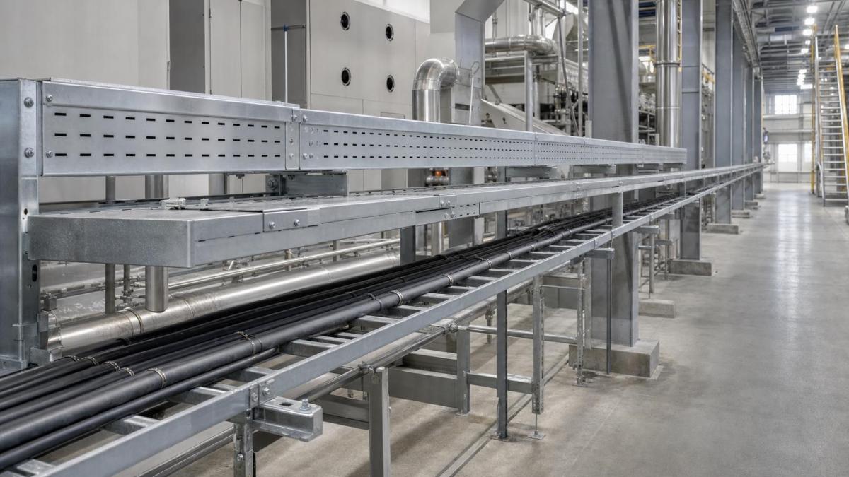
Pulp and paper mills combine wet process areas, chemical exposure, airborne fibers, high equipment loads, and long production lines. A cable support system that performs well in a dry warehouse may deteriorate quickly beside stock preparation equipment, bleaching systems, paper machines, or outdoor utility racks. For EPC contractors and plant maintenance teams, cable tray selection should therefore begin with a route-by-route environmental review, not a single material specification for the whole facility.
Why Pulp and Paper Mills Need Route-Specific Cable Management
Electrical distribution in a paper mill often crosses several conditions within one project. Main power feeders may run from a substation through outdoor pipe racks, motor cables may follow the paper machine line, and control or instrumentation cables may terminate near wet process equipment. Steam, washdown water, pulp fibers, treatment chemicals, and temperature changes create different risks along these routes.
A practical design separates the project into exposure zones. Dry electrical rooms may use pre-galvanized perforated cable tray or cable trunking. Humid production halls may require hot-dip galvanized steel or stainless steel. Areas exposed to aggressive chemicals need a finish or material confirmed against the actual chemical concentration and cleaning practice. This zoning approach controls cost while placing higher corrosion resistance where it is needed.
Choosing Cable Tray Types for Mill Services
The tray type should match the cable group, cable weight, ventilation requirement, and maintenance access. Buyers should avoid specifying one tray profile simply to reduce the number of line items.
- Cable ladder: suitable for heavy power and motor feeder routes where cable ventilation and high load capacity are priorities.
- Perforated cable tray: useful for smaller power, control, and instrumentation cables that need continuous support with some airflow.
- Wire mesh cable tray: appropriate for flexible local routing of data, communication, and lightweight control cables in dry or controlled areas.
- Cable trunking: provides enclosed protection for smaller cable groups where falling fibers, moisture, or mechanical contact must be limited.
Signal segregation also needs to be decided before widths are fixed. Power, variable-frequency drive, instrumentation, and communication cables may require separate trays or divider plates. The project electrical specification should define separation distances and any electromagnetic compatibility requirements.
Material and Surface Finish Decisions
Pre-galvanized steel can be economical for dry indoor areas with controlled humidity. Hot-dip galvanized cable tray offers a heavier zinc coating and is commonly considered for humid halls, outdoor racks, and utility areas. However, the buyer should confirm the applicable coating standard, minimum coating requirement, and treatment of cut edges and fabricated fittings.
Stainless steel may be justified near bleaching chemicals, chemical preparation systems, wastewater treatment equipment, or frequent washdown zones. Grade selection should follow the actual exposure. Stainless steel is not a universal answer: chloride content, chemical splash, crevices, and cleaning agents can affect performance. Aluminum can reduce installed weight and offers useful corrosion behavior in selected areas, but mechanical load, galvanic contact, and project fire requirements must be reviewed.
Powder coating can provide an additional protective layer or project color identification, but it should not be treated as a substitute for a suitable base material. RFQs should state the coating system, color, film thickness if required, surface preparation, and how damaged areas will be repaired during installation.
Loads, Supports, and Maintenance Access
Paper mill routes can accumulate heavy power cables over long distances. Cable weight, future cable allowance, tray self-weight, covers, and any permitted concentrated load should be included in the load assessment. Support spacing must be selected from verified tray load data rather than copied from a typical detail.
Supports near vibrating machinery deserve extra attention. Brackets, trapeze supports, strut channels, anchors, and fasteners should be coordinated with the supporting steel or concrete structure. The design should also keep trays clear of steam pipes, hot surfaces, spray zones, moving equipment, and maintenance removal paths. A low installed price has little value if a tray blocks bearing replacement or machine access.
Where fibers or process residue may collect, tray orientation and covers should allow inspection and cleaning. Covers can protect cables from falling material and liquid, but poorly ventilated covered trays may retain moisture or heat. Buyers should specify where solid, ventilated, peaked, or clamped covers are required instead of ordering covers for every route.
Fittings and Accessories Buyers Should Confirm
Long production lines require more than straight cable tray sections. The fittings schedule should be developed from routing drawings and cable bending requirements.
- Horizontal and vertical bends with suitable radii
- Tees, crosses, reducers, and risers
- Splice plates, expansion connectors, and complete fastener sets
- Divider strips for cable segregation
- Covers, cover clamps, and hold-down hardware
- Wall brackets, cantilever arms, trapeze supports, and strut channel
- Grounding and bonding jumpers where required by the electrical design
Mixed-material assemblies should be reviewed for galvanic compatibility. Stainless fasteners on galvanized steel, aluminum tray on carbon steel supports, and bonding conductors at dissimilar-metal joints may need isolation measures or a project-approved interface detail.
For large mill projects, buyers should also consider spare parts and area-based packing before the purchase order is released. A small quantity of extra splice plates, cover clamps, fasteners, and route labels can reduce delays during shutdown work or phased installation. Packing tray sections and accessories by production area, building level, or installation zone helps the site team find the correct parts without opening every bundle on arrival.
Installation Details That Affect Service Life
Drainage and cleaning access are important in wet areas. Trays should not create pockets where water, pulp, or chemical residue can remain. Field cuts and drilled holes need approved repair procedures. Installers should maintain the specified support spacing through bends and branches, and provide additional support where required by the fitting manufacturer or project standard.
Long outdoor or high-temperature routes may also need expansion provisions. Expansion joints must be located according to the expected movement and support arrangement, with bonding continuity maintained across the joint. Cable slack and cleat spacing must allow the route to move without transferring excessive force to terminations.
RFQ Checklist for Pulp and Paper Mill Projects
- Process area and route exposure: dry, humid, washdown, chemical, outdoor, or high temperature
- Cable tray type, width, side height, length, and material thickness
- Material grade and surface finish, including the required standard
- Distributed load, support spacing, future cable allowance, and any concentrated load
- Cable groups, segregation requirements, and divider quantities
- Fitting schedule with bend radii, angles, reducers, tees, and risers
- Support steel, brackets, anchors, covers, clamps, splice plates, and fasteners
- Grounding, bonding, expansion, and dissimilar-metal interface requirements
- Layout drawings, bill of quantities, packing method, and delivery sequence
Work With Hongfeng Electric
Hongfeng Electric can review cable tray schedules, route conditions, load requirements, and accessory quantities for pulp and paper mill projects. To request a quotation, send the cable list or bill of quantities together with tray dimensions, material and finish, support spacing, fitting drawings, cover requirements, and delivery destination. Clear project inputs allow HF Cable Tray to prepare a more accurate supply scope and identify missing accessories before production.
Navigation
Send Us A Message
Get in touch with us
Phone