
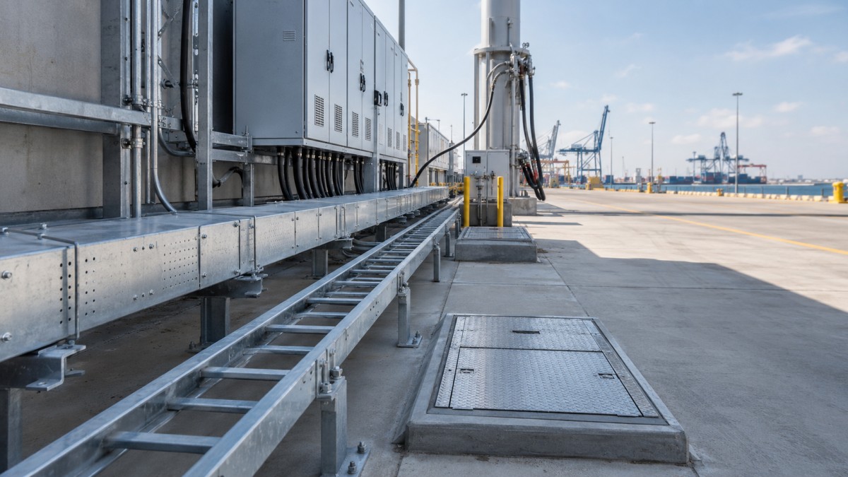
Port electrification is changing the way marine terminals plan electrical infrastructure. Shore power systems, electric cranes, charging areas, reefer container yards, lighting upgrades, pumps, communication networks, and control systems all need cable routes that can survive outdoor exposure and remain serviceable for many years. Cable tray is not the most expensive part of the electrical package, but it can become a schedule problem when it is specified too late or purchased as isolated straight lengths.
For buyers, the important question is not only which tray size is cheapest. A port cable tray package must match the route environment, cable type, load, support structure, corrosion risk, installation sequence, and future maintenance plan. A well-prepared RFQ helps suppliers quote a complete system and helps the site team avoid missing fittings, incompatible finishes, and emergency accessory orders.
Why Port Electrification Creates Demanding Cable Routes
Port and terminal electrical routes are often exposed to salt air, rain, wind, dust, vibration, and vehicle movement. Some routes run along utility corridors, equipment platforms, substations, dockside connection areas, or outdoor walls. Others pass through control rooms, pump rooms, workshops, or technical buildings. Each area can require a different tray type and surface finish.
Shore power and port electrification projects also need practical access. Cables may need inspection, thermal checking, replacement, or additional circuits as the terminal expands. If the original cable tray route is hidden behind other utilities or undersized from the beginning, future work becomes more expensive. Early coordination between the electrical designer, civil team, structural engineer, and terminal operator is therefore essential.
International buyers should also consider shipping and site logistics. Long tray sections, covers, bends, reducers, splice plates, bolts, and supports should be packed by route or zone. Port projects are often built while terminal operations continue, so installers need materials delivered in a way that supports phased work.
Selecting the Right Tray Type for Port Applications
Ladder Cable Tray
Ladder cable tray is widely used for main power routes because it provides strong mechanical support, good ventilation, and easier cable entry or exit. It is suitable for shore power feeders, substation routes, crane power routes, and longer outdoor runs when the load rating and support span are properly specified. Covers and hold-down clamps may be required where cables need protection from falling objects, weather, or wind uplift.
Perforated Cable Tray
Perforated cable tray provides more continuous cable support than ladder tray. It is often selected for smaller power cables, control cables, communication routes, lighting circuits, and equipment-area wiring. In exposed marine environments, buyers should confirm drainage, cover requirements, edge protection, and compatibility between tray sections and accessories.
Cable Trunking
Cable trunking or trough-style cable tray may be useful in control rooms, workshops, equipment shelters, and routes where cables need more enclosure. It can keep smaller circuits organized and protected, but fully enclosed routes should be reviewed for heat dissipation, condensation, and access for maintenance.
Wire Mesh Cable Tray
Wire mesh cable tray can work for data, communication, security, and low-voltage systems in indoor technical areas. It is lightweight and easy to adapt on site. For outdoor or corrosive terminal zones, buyers should confirm material, coating, support spacing, and whether the tray is acceptable under the project specification.
Material and Finish for Marine Exposure
Surface finish is one of the most important purchasing decisions in port electrification projects. Salt air and moisture can shorten the service life of poorly protected steel, especially at cut edges, punched holes, and bolted connections. The finish should be selected by route environment rather than by a single generic project assumption.
Hot-dip galvanized cable tray is often a practical choice for outdoor terminal routes because it balances strength, corrosion protection, and cost. However, buyers should not treat all galvanized products as equal. Confirm whether the tray is galvanized after fabrication, whether fittings and supports have compatible finishes, and how cut edges will be repaired during installation.
Support Design, Covers, and Accessories
A port cable tray package is only complete when it includes the support and accessory items needed for installation. Missing brackets, reducers, covers, or splice plates can delay cable pulling even when the tray lengths have arrived on site. The support package should be reviewed together with the structural route and expected cable load.
- Define support spacing based on tray type, cable load, span, and project requirements.
- Include cantilever brackets, strut channel, threaded rods, clamps, anchors, and fasteners.
- Specify covers for outdoor routes, falling-object exposure, dusty areas, or owner-required protection.
- Include horizontal bends, vertical bends, tees, crosses, reducers, end caps, and drop-out plates.
- Use hold-down clamps where wind, vibration, or movement could affect tray stability.
- Coordinate cable tray routes with pipes, ducts, crane rails, access roads, and maintenance walkways.
Buyers should also check whether the support finish matches the tray finish. A corrosion-resistant tray installed with poorly protected brackets or mixed fasteners can still create weak points in the system.
RFQ Checklist for Port Buyers
For overseas procurement, a clear RFQ reduces misunderstandings and makes quotations easier to compare. Instead of requesting only width, height, and thickness, buyers should describe the route, environment, load, and required accessories.
- Project area: shore power berth, substation, reefer yard, crane route, control room, or workshop.
- Tray type: ladder tray, perforated tray, trunking, or wire mesh tray.
- Size and material: width, side height, thickness, standard length, steel grade, and finish.
- Route environment: indoor, outdoor, coastal, high humidity, chemical exposure, or public-adjacent area.
- Accessory schedule: bends, tees, reducers, covers, splice plates, end caps, clamps, and drop-outs.
- Support package: brackets, strut channel, threaded rods, anchors, bolts, nuts, and washers.
- Packing method: route labels, bundled accessories, phased delivery, and spare hardware allowance.
Final Buying Advice
Port electrification and shore power projects need cable tray systems that are strong, corrosion-resistant, and easy to maintain. The lowest unit price for straight tray lengths does not necessarily produce the lowest installed cost. Buyers should review the tray body, surface finish, supports, covers, fittings, fasteners, and packing plan as one integrated package.
HONGFENG / Cable Tray Pro supplies ladder cable tray, perforated cable tray, cable trunking, wire mesh cable tray, hot-dip galvanized cable tray, stainless steel cable tray, and matched accessories for industrial and infrastructure projects. Send your route drawings, environmental requirements, quantity list, and packing preferences to prepare a practical quotation for your port electrification project.