
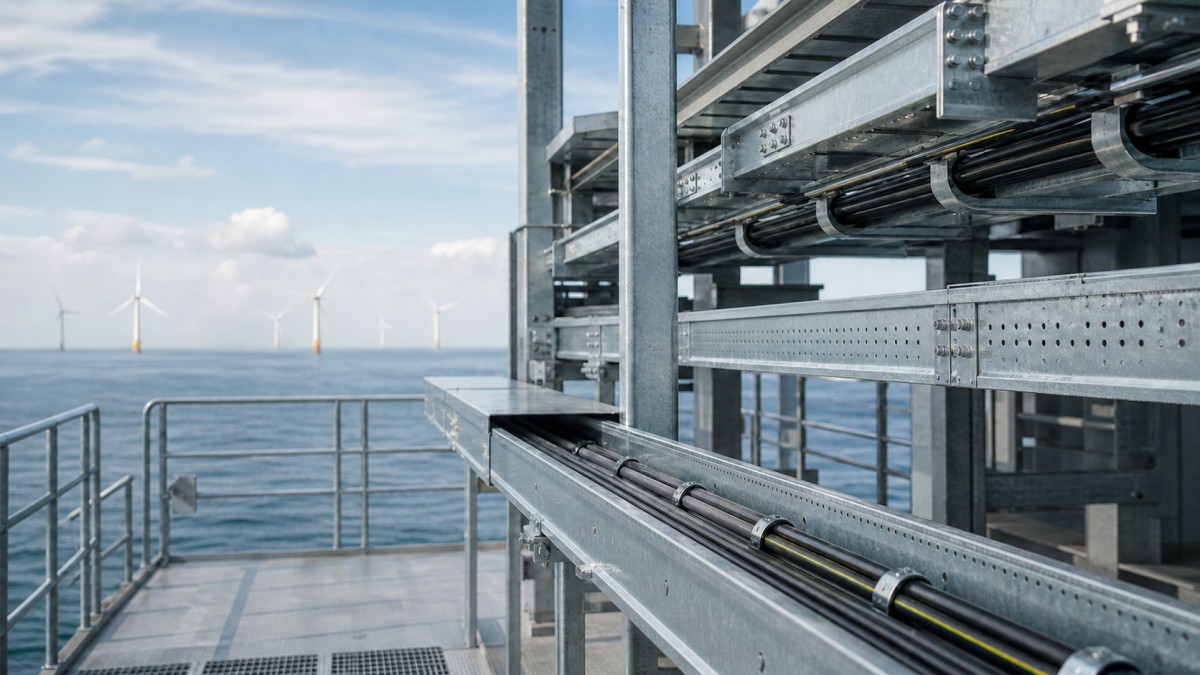
Offshore wind projects place cable systems in a demanding combination of marine exposure, restricted access, vibration, heavy equipment, and complicated interfaces between turbines, offshore substations, export cables, and onshore electrical facilities. Cable tray is only one part of the electrical route, but its material finish, support arrangement, fittings, and access strategy can affect installation time and long-term maintenance.
For EPC contractors and overseas buyers, the right approach is to specify the cable tray system by service area rather than purchase one finish for the whole project. An open tray may suit a protected equipment deck, while a covered or stainless system may be more appropriate near salt spray, chemical cleaning, or exposed cable transitions.
Project Conditions That Change Tray Selection
An offshore wind cable route is not a single environment. Inside an enclosed electrical room, the main concern may be cable loading, separation, and access. On an open platform, the system must also tolerate wind-driven moisture, salt-laden air, spray, temperature changes, and frequent inspection. Onshore transition areas may combine outdoor exposure with buried or enclosed routes.
Before choosing a tray, the design team should identify the location, cable group, support span, access method, and expected maintenance activity. The following questions help turn a general cable tray request into a usable procurement scope:
- Is the route inside an enclosed room, under a canopy, on an open deck, or close to direct sea spray?
- Does the route carry large power cables, control cables, communication cables, or mixed services?
- Will technicians need to open covers, pull additional cables, or replace fittings during planned maintenance?
- Are the tray and support structures attached to steel platforms, concrete foundations, cable bridges, or equipment skids?
- Do the project documents require a specific material, finish, coating repair method, or inspection record?
Selecting the Right Tray Type
Ladder Cable Tray for Main Power Routes
Ladder cable tray is often the first option to review for main power routes because the rungs provide regular cable support and convenient access from above or below. It can be suitable for turbine auxiliary power, substation feeder routes, and longer runs where ventilation and cable pulling access are important. The final selection still depends on cable diameter, loading, support span, bend radius, and the project engineer's installation method.
Perforated Cable Tray for Control and Auxiliary Services
Perforated tray provides more continuous bottom support and can be useful for control, instrumentation, lighting, and smaller power cables. The perforations also help with drainage and fixing points. Buyers should review hole pattern, side-rail height, and accessory compatibility, especially where cable clamps, separators, or small branch fittings are required.
Covered Tray and Enclosed Trunking at Vulnerable Interfaces
Covers can reduce direct exposure to falling debris, spray, and accidental contact, but they also add weight and may affect heat dissipation and inspection access. Enclosed trunking is useful for smaller protected branches, instrument cables, or routes where a cleaner enclosure is required. It should not be selected automatically for every route; drainage, condensation, cable temperature, and future access must be considered.
Materials and Marine Corrosion Protection
Hot-dip galvanized steel is commonly considered for outdoor and industrial routes because the coating provides a practical corrosion barrier and the steel offers strong mechanical performance. The buyer should still confirm the actual galvanizing process, coating quality, drain and vent details, cut-edge treatment, and compatibility of splice plates, bolts, washers, supports, and covers.
Stainless steel may be selected for highly exposed, washdown, or aggressive service areas when the project specification supports it. The grade, fastener material, fabrication method, and surface condition should be reviewed as a complete system. Mixing a corrosion-resistant tray with unsuitable fasteners or brackets can create weak points that are easy to miss during quotation review.
| Service area | Tray approach | Buying checks |
|---|---|---|
| Enclosed electrical room | Ladder or perforated tray based on cable group | Load, span, separation, bend radius, access |
| Open offshore platform | Marine-finish tray with selected covers | Corrosion, wind exposure, fixings, drainage |
| Control and instrumentation route | Perforated tray or enclosed trunking | Cable separation, shielding, branch fittings |
| Onshore transition and cable bridge | Heavy-duty tray with covers where exposed | Expansion, interface dimensions, support detail |
Support, Vibration, and Maintenance Access
A tray that is correctly sized but poorly supported can still create installation and maintenance problems. Support spacing should be coordinated with the tray manufacturer's load tables, the cable weight, the support geometry, and the most demanding straight and bend sections. The RFQ should show whether the supplier is expected to provide cantilever brackets, trapeze supports, vertical supports, hold-down clamps, and connection hardware.
Offshore routes also need a practical response to movement and vibration. This does not mean adding random reinforcement. The engineering team should identify equipment interfaces, long straight runs, access covers, and locations where a rigid connection could transfer movement into cable terminations. Supports should leave enough clearance for inspection, cable pulling, bolt tightening, and future replacement.
At bends and vertical changes, use purpose-made elbows, risers, reducers, and splice plates rather than forcing a straight tray into position. Large power cables need a controlled bend radius and adequate support through the fitting. This is one area where a complete accessory schedule is often more valuable than a low tray-only price.
Cable Separation and Export Cable Interfaces
Offshore wind facilities contain power, control, communication, protection, lighting, and auxiliary circuits. The final segregation method belongs to the project design, but the tray system must support it through separate routes, dividers, vertical levels, or specified spacing. A single wide tray is not automatically a complete cable management solution if the route contains incompatible cable groups.
The interface between internal tray routes and export or array cable systems deserves early coordination. Cable entry points, pulling directions, gland plates, termination cabinets, and equipment openings should be checked against tray width, side-rail height, cover clearances, and bend fittings. Late changes at these interfaces often result in field cutting, extra support steel, or incompatible replacement fittings.
For international procurement, drawings should identify the tray family, width, height, material finish, support type, fitting angle, and connection method. A clear schedule lets the buyer compare offers and reduces the risk that one supplier prices only straight lengths while another includes a complete installed system.
Delivery, Inspection, and Site Installation
Marine projects can have long logistics routes and limited installation windows, so packing and identification deserve attention. Straight lengths, fittings, covers, and support components should be packed by route or installation area where practical. Each bundle should be clearly identified so the site team can locate the correct fitting without opening every package. This is especially useful when work is split between fabrication yards, offshore assembly, and onshore transition facilities.
Before installation, inspect the tray surface, hole pattern, side rails, splice plates, fasteners, and covers. Confirm that field cutting and drilling follow the project method and that any damaged protective finish is repaired with an approved process. A short inspection record with photographs, quantities, and nonconformity notes can help the EPC team close out the package and control replacement orders.
Offshore Wind Cable Tray Procurement Checklist
- Define each service area and environmental exposure instead of using one finish across all routes.
- List tray type, width, side-rail height, thickness, straight length, and cover requirements.
- Include elbows, tees, crosses, risers, reducers, splice plates, dividers, covers, clamps, and support steel.
- Request coating or material documentation, dimensional drawings, loading information, and packing details.
- Confirm how damaged coating, cut edges, field drilling, and stainless fabrication areas will be treated.
- Check that the proposed system is compatible with cable glands, supports, earthing or bonding details, and equipment interfaces.
The best buying decision is usually the offer that makes the complete route clear: tray, fittings, supports, covers, finish, documentation, and delivery packaging. HONGFENG / Cable Tray Pro can support project teams with cable ladder, perforated tray, trunking, accessories, and customized schedules for industrial and infrastructure applications. Send the route drawings, cable groups, environmental conditions, and required quantities for a practical quotation review.
Navigation
Send Us A Message
Get in touch with us
Phone