
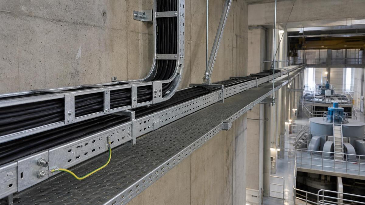
Hydroelectric projects place cable routes across several very different environments. A single plant may include a relatively clean control room, a humid turbine hall, drainage galleries, vertical shafts, outdoor transformer connections, and service tunnels exposed to condensation. Treating all of these areas as one cable tray application often leads to inconsistent finishes, unnecessary product variety, or accessories that do not match the installation conditions.
For EPC contractors and project buyers, the practical task is to divide the route into operating zones and specify each zone according to cable duty, moisture exposure, support conditions, and maintenance access. This approach produces a clearer bill of quantities and gives cable tray suppliers enough information to quote a coordinated system rather than isolated straight sections.
Map the Cable Routes by Plant Area
The cable tray schedule should identify where each route begins and ends, not only its width and depth. Power cables from generators and auxiliary systems can create heavy loading in turbine and electrical rooms. Control, protection, and instrumentation cables may run through galleries where frequent access and later modifications are expected. Outdoor transitions can experience rain, temperature changes, and airborne contaminants, while underground spaces may remain damp even when they are not directly exposed to water.
A useful route classification separates dry indoor rooms, humid indoor areas, wet or washdown areas, outdoor sections, vertical risers, and interfaces with equipment supplied by other vendors. The classification can then be linked to the required tray type, material or coating, cover arrangement, support design, and bonding details.
Select the Tray Type According to Cable Duty
No single cable support format suits every hydroelectric plant route. The selection should follow cable weight, required ventilation, mechanical protection, routing density, and the frequency of branch connections.
- Cable ladder is commonly considered for heavy power and auxiliary cables where open ventilation, high load capacity, and straightforward cable fixing are important.
- Perforated cable tray can support control and smaller power cables while providing more continuous support and a practical surface for cable grouping.
- Wire mesh cable tray may suit lighter communication, data, or local instrumentation routes in dry, accessible rooms where field changes are common.
- Cable trunking provides enclosed protection for smaller cable groups in locations where mechanical contact, dust, or falling debris requires additional control.
Transitions between these systems should be shown on drawings. A ladder route that narrows into a perforated tray near a control panel needs a defined reducer, support point, cable fixing method, and bonding connection. Leaving these details to site improvisation increases installation time and makes the final route harder to inspect.
Match Material and Finish to Moisture Exposure
Condensation is one of the main specification issues in hydroelectric facilities. A gallery can appear dry during construction but experience persistent moisture after the plant begins operation. Project buyers should confirm the expected humidity, direct water exposure, chemical cleaning conditions, and outdoor exposure for every tray zone.
Pre-galvanized steel may be considered for controlled indoor areas where corrosion exposure is limited. Hot-dip galvanized steel is often evaluated for more demanding indoor or outdoor service because the completed steel components receive a heavier protective zinc coating. Stainless steel or another project-approved corrosion-resistant material may be justified in continuously wet zones, aggressive atmospheres, or areas where coating repair would be difficult.
The finish description should cover fittings, splice plates, brackets, threaded components, and fasteners as well as straight tray sections. Mixing a corrosion-resistant tray with lower-grade accessories creates weak points. Cut edges and field-drilled holes also need a project-approved treatment method.
Plan for Vibration, Vertical Runs, and Drainage
Equipment vibration and the movement of large cables affect support and fixing decisions near turbines, generators, pumps, and transformers. The tray route should avoid transferring equipment movement into long rigid runs. Where flexible interfaces or independent supports are required, they should be coordinated with the equipment vendor and structural designer.
Vertical shafts need particular attention. Cable weight must be restrained by suitable cleats or clamps rather than carried by the tray alone. Buyers should provide vertical rise height, cable type, cable outside diameter, fixing interval required by the cable design, and access constraints. Covers on vertical or inclined routes also require secure fastening that remains serviceable.
In damp areas, enclosed sections should not unintentionally trap water. The design team should decide whether covers are required for falling water or mechanical protection and how drainage and ventilation will be maintained. Cover type, hold-down clips, stand-off arrangements, and any drain provisions should appear in the accessory schedule.
Coordinate Supports, Fittings, and Bonding
Support spacing cannot be selected from tray width alone. It depends on cable weight, tray construction, fitting locations, concentrated loads, maintenance practice, and the project design criteria. Bends, tees, reducers, risers, and long vertical sections often need support positions different from those used along a straight run.
The procurement package should include the complete route hardware: cantilever arms, trapeze supports, channels, brackets, splice plates, fasteners, hold-down clamps, cable cleats, covers, dividers, bends, tees, reducers, and bonding accessories. Confirm whether strut channel and support steel are in the cable tray supplier's scope or another contractor's package.
Electrical continuity and protective bonding must follow the project's electrical design and local requirements. Buyers should state whether dedicated bonding jumpers, grounding connectors, or continuity-tested splice arrangements are required. The requested hardware should be compatible with the selected tray material and coating.
RFQ Information for a Hydroelectric Project
A supplier can prepare a more reliable quotation when the inquiry includes route conditions as well as dimensions. The following information should accompany the tray schedule and drawings:
- Plant area and environment classification for each route
- Tray type, width, side height, material thickness, and required straight length
- Material and surface finish for trays, fittings, supports, and fasteners
- Cable type, total cable weight, load requirement, and proposed support spacing
- Horizontal and vertical bends, tees, crosses, reducers, and equipment interfaces
- Cover requirements, fastening method, drainage concerns, and outdoor exposure
- Vertical cable fixing, bonding accessories, and any seismic or vibration criteria
- Drawings, tag numbering, packing sequence, inspection documents, and delivery stages
Work With Hongfeng Electric
Hongfeng Electric can review cable tray schedules and layout drawings for hydroelectric power plant packages, including cable ladder, perforated cable tray, cable trunking, strut channel, supports, fittings, covers, and bonding accessories. For a project quotation, send the route drawings, cable load data, dimensions, finish requirements, accessory list, and delivery plan. The review can then focus on practical system compatibility and a complete supply scope for site installation.
Navigation
Send Us A Message
Get in touch with us
Phone