
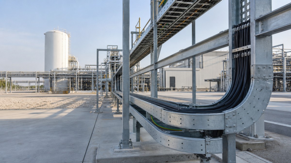
Green ammonia projects combine high-capacity electrical systems with chemical-process equipment. Electrolyzers, air-separation units, compressors, ammonia synthesis equipment, water treatment, storage systems, utilities, substations, and control buildings may be delivered by different package vendors. Their cables eventually share plant corridors, pipe racks, module interfaces, and building entries, making cable tray coordination a project-wide task rather than a minor electrical detail.
For EPC contractors and overseas procurement teams, the main risk is fragmentation. A tray ordered only from preliminary cable quantities may not include the fittings, supports, barriers, covers, fasteners, bonding parts, and transition details needed when package information is finalized. A better approach divides the facility into service zones, assigns cable groups and tray duties, and then builds a complete procurement schedule around verified loads and interfaces.
Divide the Facility into Electrical Route Zones
The electrolyzer area can contain large DC and AC power connections, cooling and water-treatment auxiliaries, control wiring, and numerous equipment interfaces. The air-separation and ammonia-process areas add compressors, pumps, analyzers, valves, and instrument systems. Storage and loading areas may have long outdoor routes, while substations and control rooms concentrate cable entries in relatively small spaces.
These areas should not be treated as one uniform environment. Each route segment needs a defined cable service, physical exposure, material requirement, expected load, support arrangement, and interface owner. The project's hazardous-area classification and electrical design may also place specific requirements on equipment, wiring methods, separation, bonding, and installation. Cable tray selection must follow those approved documents; tray alone does not establish whether an installation is suitable for a classified area.
A zone-based schedule also helps when packages arrive in stages. Main pipe-rack routes can be sized and procured with controlled spare capacity, while local branches remain tied to approved vendor drawings. This reduces late field cuts and makes responsibility at module boundaries easier to understand.
Select Tray Types for Power, Control, and Instrumentation
Ladder Tray for Main Power Distribution
Ladder cable tray is a practical starting point for large power feeders between substations, rectifier or power-conversion equipment, compressors, pumps, and other major loads. Its open construction supports ventilation and cable access. The final selection must match cable weight, cable grouping, side-rail strength, rung arrangement, proposed support span, and the geometry of vertical and horizontal fittings.
Perforated Tray for Smaller Cable Groups
Perforated tray provides more continuous support for control, instrumentation, auxiliary, and communication cables. It can be installed as a separate tier or route where the approved design requires physical separation from power cables. Buyers should confirm the perforation pattern, usable internal dimensions, cover type, divider arrangement, and cable entry accessories.
Cable Trunking at Equipment and Building Interfaces
Cable trunking may suit selected indoor branches, analyzer shelters, local control panels, and routes requiring additional protection. Enclosed systems need planned entries and removable access. Outdoor or process-area use also requires attention to drainage, condensation, heat dissipation, and the approved material specification.
Plan Segregation and Package Interfaces Early
Green ammonia facilities can have many cable categories: high- and low-voltage power, DC power, motor feeders, controls, instrumentation, communication networks, fire and gas systems, and other project-defined services. The required separation cannot be decided from a generic tray catalog. It must come from the project's electrical philosophy, cable schedules, equipment requirements, and applicable rules.
Once that basis is approved, the tray system can provide separate tiers, distinct routes, or barriers as needed. Physical separation must continue through bends, tees, risers, reducers, and building penetrations. A divider that stops before every fitting does not deliver a coordinated route. Procurement schedules should therefore identify barrier lengths and fitting-specific barrier pieces rather than listing a single bulk quantity.
Package boundaries deserve particular attention. Skid vendors may terminate cables at local junction boxes, deliver short tray sections, or expect the site contractor to provide all external routes. Interface drawings should show tray elevation, direction, width, material, cable entry side, and responsibility for the final support. Where modules are assembled off site, dimensional tolerances and field-adjustable transition pieces may prevent expensive rework.
Match Material and Finish to the Process Environment
Outdoor exposure, coastal air, cooling-water systems, chemical treatment areas, and cleaning practices can create different corrosion conditions within the same plant. Material selection should be based on the site environmental assessment and owner specification. It should include the entire support path, not only the tray body.
| Route Environment | Design Focus | Buyer Questions |
|---|---|---|
| Clean indoor electrical rooms | Cable density, panel entries, future capacity | Is the specified finish compatible with all fittings, supports, and bonding parts? |
| Outdoor process and pipe racks | Weather, drainage, long runs, structural movement | Is galvanizing performed after fabrication, and are covers and expansion details defined? |
| Wet or chemically exposed zones | Corrosion resistance and material compatibility | Do tray, brackets, splice plates, bolts, washers, and clamps use the approved material system? |
| Module and skid interfaces | Mixed finishes, dimensional tolerance, site connections | Who supplies the transition, final support, matching hardware, and field repair material? |
Hot-dip galvanized tray may be suitable for many outdoor industrial routes when approved for the site condition. Stainless steel or another project-approved corrosion-resistant system may be required in more aggressive areas. Mixing dissimilar metals without engineering review can create durability problems, particularly at fasteners and contact points. Suppliers should state base material, manufacturing process, finish, and included hardware clearly.
Coordinate Supports, Pipe Racks, and Maintenance Access
Pipe racks are valuable shared corridors, but tray cannot simply occupy whatever space remains after piping. Electrical routes need access for cable installation, inspection, and replacement. They should remain clear of hot surfaces, valve-removal zones, lifting paths, drains, and locations where leaks or routine maintenance could affect cables. Structural loads and attachment points must be agreed with the rack designer.
Support spacing must match the verified tray load data and site load combinations. Bends, tees, reducers, vertical risers, and cable-drop locations often require additional support. Long outdoor runs may also need engineered provisions for movement between structures. The tray supplier can provide system information, but the project engineer remains responsible for support and anchor design.
Maintenance planning should preserve removable covers, cable access, and safe working space. Analyzer shelters, compressor packages, and electrolyzer modules can change during design development, so local branches should allow controlled adjustment without compromising the main route. A coordinated model helps, but key elevations, dimensions, and responsibility points still belong on issued drawings and schedules.
Green Ammonia Cable Tray Procurement Checklist
- Divide tray quantities by plant area, cable service, material, finish, width, and side-rail height.
- State cable loads, support spans, concentrated loads, and any project-specific mechanical requirements.
- Follow the approved cable segregation, hazardous-area, bonding, and installation documents.
- Identify package boundaries and responsibility for transitions, final supports, and local branches.
- Include bends, tees, reducers, risers, barriers, covers, splice hardware, clamps, and support steel.
- Verify material compatibility across tray, fittings, supports, fasteners, and module interfaces.
- Request shop drawings, dimensional tolerances, load information, finish documentation, and packing lists.
- Reserve future capacity only where plant expansion or additional packages are realistically expected.
Final Buying Advice
A reliable green ammonia cable tray package begins with interfaces, not catalog dimensions. Buyers should compare bids using the same route schedule and confirm that every supplier has included compatible fittings, supports, covers, barriers, hardware, and documentation. This approach improves technical comparison and reduces field improvisation as process packages are finalized.
HONGFENG / Cable Tray Pro can support contractors and procurement teams by reviewing cable tray schedules, material requirements, fitting quantities, and packing needs for international projects. Final tray selection and installation details should be approved by the project engineering team in accordance with the site conditions, owner requirements, and applicable rules.
Navigation
Send Us A Message
Get in touch with us
Phone