
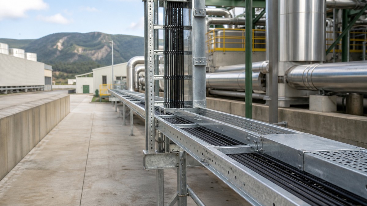
Glass manufacturing is a continuous industrial process with sharply different electrical environments. Raw-material handling, melting furnaces, forming lines, annealing equipment, inspection systems, compressors, utilities, cullet handling, and packing areas all need dependable cable routes. High process temperatures and restricted shutdown opportunities make route planning more important than simply choosing a tray width.
Modernization projects can add electric boosting, hybrid furnace equipment, new drives, sensors, emissions-control systems, or automated inspection. These additions increase cable density and create interfaces with operating production lines. For engineers and procurement teams, a complete cable tray package should address heat exposure, dust, vibration, maintenance access, cable separation, supports, fittings, and phased installation from the beginning.
Map the Production Process before Selecting Tray
Batch houses and cullet systems include conveyors, mixers, elevators, feeders, dust collection, and many local motors. Furnace buildings introduce radiant heat, burner or electrical equipment, large ventilation systems, and dense mechanical services. Forming and annealing areas add drives, controls, cooling, inspection, and synchronized production equipment. Cold-end and packing zones are generally cleaner but can require frequent branch changes for automation.
Each zone should have a defined tray duty. Main distribution and large motor feeders may require heavy-duty ladder tray. Control, instrumentation, and communication routes may use perforated tray or trunking. Local machine connections can need flexible interfaces or short protected branches. The project should also identify which tray is supplied with furnace, forming, emissions-control, and packaging packages.
A route schedule gives procurement a consistent basis. It should record tray type, width, side-rail height, material, finish, cable load, support span, cover requirement, divider needs, fitting quantity, and installation phase. Routes near furnaces, batch dust, washdown, outdoor utilities, or equipment-removal zones should be clearly flagged.
Match Tray Type to Cable Size and Process Duty
Ladder Tray for Power Distribution
Ladder cable tray is a practical option for large motor feeders, main electrical distribution, furnace auxiliaries, fans, compressors, and major drives. Its open construction supports ventilation and inspection. Selection should be based on actual cable weight, cable grouping, side-rail capacity, rung arrangement, support span, and fitting loads rather than sheet thickness alone.
Perforated Tray for Controls and Automation
Perforated tray provides more continuous support for control, instrumentation, sensor, communication, inspection, and smaller auxiliary cables. A dedicated route or tier can help preserve the separation required by the approved electrical design. Buyers should include covers, dividers, drop-outs, vertical transitions, and compatible fittings where needed.
Trunking for Local Protected Circuits
Cable trunking can be useful around machine control stations, inspection equipment, and cleaner cold-end areas where smaller cable groups need additional protection. Enclosed routes require access for additions and fault finding. In dusty or hot zones, the project must consider sealing philosophy, heat dissipation, cable entries, and cleaning methods before selecting trunking.
Manage Heat without Relying on Covers Alone
Furnace-area cable tray should be positioned from a thermal route study, not from the remaining space in the ceiling. Radiant heat, hot ductwork, flues, furnace walls, and process openings can raise local cable temperature even when room air appears acceptable. The electrical design should use the actual ambient and grouping conditions, cable data, and equipment requirements.
Distance and physical routing are usually more dependable than assuming a metal cover will solve heat exposure. A cover can protect against falling material or direct contamination, but it may also reduce ventilation and make inspection more difficult. Heat shields, where required by engineering, need independent support and enough clearance to avoid transferring heat directly into the tray.
Tray should also remain clear of furnace maintenance doors, burner access, electrode or booster equipment, crane movements, refractory repair zones, and removable machine components. A route that blocks shutdown maintenance can cost far more than a longer tray alignment. Reviews should include operations and maintenance personnel, not only the model coordination team.
Select Finish for Dust, Moisture, and Outdoor Exposure
Many glass plants contain both dry dusty zones and wet or outdoor utilities. Batch materials and cullet fines can accumulate on horizontal surfaces, while cooling-water, compressor, and treatment areas may introduce moisture. The approved material and finish should therefore be assigned by plant area. Cleaning practices and the potential for abrasion or coating damage should be included in the review.
| Plant Zone | Route Challenge | Buying Focus |
|---|---|---|
| Batch and cullet handling | Dust, abrasion, conveyors, frequent motor branches | Confirm cleaning access, covers where justified, branch fittings, supports, and finish durability. |
| Furnace and hot process areas | Radiant heat, dense services, shutdown maintenance | Verify route temperature, clearances, independent supports, ventilation, and access to furnace equipment. |
| Forming, annealing, and inspection | Drives, sensors, synchronized equipment, cable segregation | Define separate power and control routes, machine interfaces, drops, and future automation capacity. |
| Cooling, treatment, and outdoor utilities | Moisture, chemicals, weather, long runs | Review complete corrosion system, drainage, compatible hardware, support span, and cover fastening. |
Hot-dip galvanized steel may suit many industrial and outdoor routes where it meets the project requirements. Pre-galvanized tray may be acceptable in approved dry, controlled areas. Stainless steel or another corrosion-resistant system may be needed in aggressive wet or chemical zones. Tray bodies, fittings, brackets, fasteners, splice plates, covers, and bonding parts should use compatible materials.
Plan Supports for Vibration, Loads, and Maintenance
Fans, compressors, conveyors, crushers, and forming equipment can introduce vibration. Cable tray should not be attached directly to vibrating machinery unless the approved equipment design provides a suitable interface. Independent supports and controlled flexible transitions can prevent equipment movement from being transferred into long tray runs.
Support spacing must match the selected tray load data and the project's structural load cases. Wider or deeper tray is not automatically stronger if the bracket or channel system is inadequate. Horizontal and vertical bends, tees, reducers, risers, cable drops, and concentrated cable groups may need additional support. Support locations should also avoid access doors, crane paths, and removable roof or wall panels.
Brownfield furnace upgrades require an installation sequence that respects continuous production. Prefabricated support assemblies, clearly tagged tray sections, and verified field dimensions can reduce work near operating equipment. The procurement package should separate early structural items from final tray fittings where equipment data is still developing, while preserving compatibility across both orders.
Glass Plant Cable Tray RFQ Checklist
- Divide tray quantities by batch house, furnace, forming, annealing, cold-end, packing, and utility areas.
- State tray type, dimensions, load, support span, material, finish, covers, and divider requirements.
- Use verified local temperature and cable data for routes near furnaces, flues, hot ducts, and forming equipment.
- Preserve separation for power, drive output, control, instrumentation, communication, and safety-related services as designed.
- Include bends, tees, reducers, risers, drop-outs, barriers, covers, splice hardware, clamps, and support components.
- Identify dust, washdown, chemical, outdoor, vibration, and equipment-maintenance zones.
- Clarify interfaces with furnace, forming, inspection, emissions-control, and packing equipment vendors.
- Request dimensional drawings, load data, finish records, accessory lists, installation information, and packing labels.
Final Buying Advice
Cable tray for a glass plant should be selected around process conditions and maintenance reality. Unit price matters, but system completeness, verified load performance, thermal routing, material compatibility, fitting quality, and installation documentation often determine the final project cost. A zone-based schedule allows bidders to quote the same scope and makes substitutions easier to evaluate.
HONGFENG / Cable Tray Pro can review cable tray schedules, route environments, fittings, supports, and export packing requirements for glass manufacturing projects. Final tray location, material, support design, and cable arrangement should follow the approved project documents, equipment supplier instructions, and applicable local requirements.
Navigation
Send Us A Message
Get in touch with us
Phone