
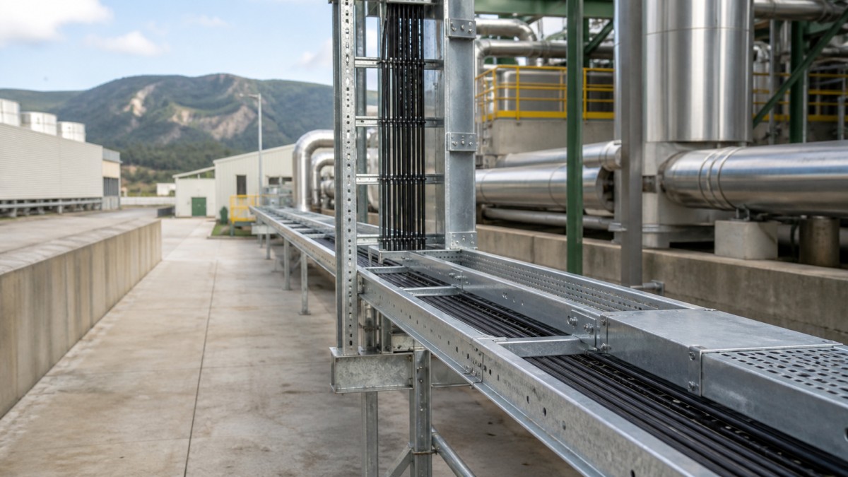
Geothermal power plants combine power-generation equipment with hot fluids, outdoor wellfield routes, cooling systems, chemical treatment, and continuous operating requirements. Dry-steam, flash-steam, and binary-cycle plants use different process arrangements, but each depends on reliable power, control, instrumentation, communication, and auxiliary cable routes. A cable tray system must support those circuits without creating conflicts with hot piping, brine handling, equipment access, or future well connections.
For EPC contractors and international buyers, the main procurement challenge is variation across the site. An indoor electrical room, an outdoor steam gathering corridor, a cooling area, and a chemical dosing skid should not automatically receive the same tray material or accessory package. A route-based specification makes the environmental assumptions visible and reduces gaps between straight tray, fittings, supports, covers, fasteners, and bonding components.
Divide the Geothermal Facility into Route Zones
The wellfield and gathering system can involve long outdoor runs between production wells, separators, heat exchangers, and the power block. These routes may cross uneven terrain or separate foundations and may remain exposed to rain, sunlight, wind, dust, and geothermal vapors. The power block concentrates generator, turbine, pump, fan, and auxiliary feeders, while control buildings bring many smaller cables into panels and distributed control equipment.
Cooling and reinjection systems add pumps, fans, valves, analyzers, and local instruments. Chemical treatment areas may have a different corrosion environment from the general plant. Binary-cycle equipment can also introduce packaged skids and closely spaced heat exchangers, so interfaces between vendor-supplied and site-installed tray need clear ownership.
A practical tray schedule identifies area, cable service, tray type, width, side-rail height, material, finish, expected load, support concept, cover requirement, and fitting allowance. It should also flag transitions between structures, vertical risers, hot zones, chemical exposure, and locations where future wells or generation modules could connect.
Choose Tray Type by Cable Duty
Ladder Tray for Main Power and Motor Feeders
Ladder cable tray is commonly evaluated for generator auxiliaries, large pumps, cooling fans, transformers, and plant distribution feeders. Its open construction supports ventilation and practical cable access. The selected side rail, rung arrangement, fitting geometry, and support span must be checked against the actual cable load and the project's mechanical design conditions.
Perforated Tray for Control and Instrumentation
Perforated cable tray gives more continuous support to smaller control, instrumentation, communication, and monitoring cables. It can be installed on a separate tier or route where the approved design requires physical separation from power cables. Buyers should specify usable internal dimensions, perforation pattern, dividers, covers, drop-outs, and matching fittings rather than relying on a generic product name.
Trunking for Selected Local Branches
Cable trunking can suit protected indoor branches, analyzer shelters, local control panels, and compact equipment interfaces. In outdoor or humid service, enclosed routes require planned drainage, cable entries, removable access, and consideration of heat buildup. Trunking should be selected by location instead of used as a universal replacement for open tray.
Select Material and Finish for Real Exposure
Geothermal fluids vary by resource, and plant exposure can include moisture, salts, process chemicals, or gases that affect material durability. Cable tray should not be specified from the energy source label alone. The owner and project engineer need to define the corrosion environment for each area, including expected contact with condensation, leakage, washdown, airborne contaminants, and outdoor weather.
| Route Environment | Typical Concern | Procurement Check |
|---|---|---|
| Indoor electrical and control rooms | Cable density, panel entries, future capacity | Confirm approved indoor finish, separation, supports, drop-outs, and spare route space. |
| Outdoor wellfield and gathering routes | Weather, long runs, terrain, structural movement | Verify finish after fabrication, support span, covers, drainage, expansion details, and anchorage responsibility. |
| Brine, cooling, or chemical-treatment areas | Moisture, salts, chemical exposure, washdown | Review tray, fittings, support steel, fasteners, clamps, and bonding parts as one compatible material system. |
| Turbine and process equipment zones | Heat, vibration, maintenance, equipment packages | Confirm clearances, independent supports, fitting strength, transition ownership, and removable access. |
Hot-dip galvanized steel may be appropriate for many outdoor industrial routes when it meets the site specification. Stainless steel or another approved corrosion-resistant material may be more suitable in aggressive local zones. The grade, fastener material, support finish, and contact between dissimilar metals require coordinated review. A durable tray body paired with incompatible bolts or brackets does not create a durable system.
Maintain Clearance from Heat and Process Piping
The shortest route is not always the best route. Cable tray should remain clear of hot surfaces, pressure-relief discharge paths, valves requiring access, pipe supports, drains, and areas where process leakage could reach cables. Insulation does not remove the need for an engineering clearance review because pipe movement, maintenance, and local surface conditions can change over time.
Tray supports should be independent of process piping unless an approved design specifically provides otherwise. Attaching electrical supports to a pipe support can introduce unverified loads and make maintenance responsibility unclear. Where tray crosses between structures or packaged units, the design should consider relative movement and construction tolerance instead of forcing rigid field connections.
Covers can protect selected outdoor routes from falling debris or direct exposure, but they should be assigned by area. Covers affect cable access and ventilation, and they need secure fastening where wind is a concern. Drainage openings and cable-entry details should direct moisture away from equipment rather than trap it inside a covered route.
Coordinate Supports, Fittings, and Cable Installation
Tray load capacity is linked to the proposed support span. Buyers should request supplier data for the selected tray profile and compare it with the project cable load and support arrangement. Bends, tees, reducers, vertical risers, heavy cable drops, and route terminations often need additional support. Fittings should not be left suspended between supports designed only for straight lengths.
Long outdoor runs also need practical cable pulling access. Route drawings should show bend direction, available pulling space, equipment entry, and any locations requiring large-radius fittings. A route may fit geometrically while still being impossible to cable without temporary removal of pipework or handrails. Constructability reviews should therefore include the installation sequence and future cable replacement.
The complete bill of materials should cover straight tray, horizontal and vertical bends, tees, reducers, splice plates, divider systems, covers, hold-down clamps, drop-outs, bonding accessories, fasteners, brackets, channels, and anchor interfaces. Vendor packages should use compatible tray geometry at the boundary or provide an approved transition detail.
Geothermal Cable Tray RFQ Checklist
- Issue an area schedule showing tray type, dimensions, material, finish, covers, cable load, and support span.
- Identify wellfield, steam or brine, cooling, chemical, electrical-room, and packaged-equipment routes separately.
- Define cable segregation and bonding requirements from the approved electrical design.
- Confirm environmental compatibility for tray, fittings, supports, fasteners, clamps, and bonding parts.
- Include fitting-specific supports, large-radius bends, vertical transitions, and cable drop accessories.
- Check clearance from hot piping, maintenance zones, drains, relief paths, and equipment-removal routes.
- Clarify interfaces between site tray, turbine packages, binary-cycle skids, cooling equipment, and wellfield systems.
- Request dimensional drawings, load data, material and finish records, accessory lists, and packing identification.
Final Buying Advice
A geothermal cable tray package should be evaluated as an engineered route system, not a price per meter. The most useful bids show how tray strength, finish, fittings, supports, covers, hardware, and documentation respond to each plant zone. This makes technical comparison clearer and reduces field improvisation around process equipment.
HONGFENG / Cable Tray Pro can review project tray schedules, environmental requirements, fitting quantities, and export packing needs for geothermal projects. Final material selection, support design, cable arrangement, and installation must follow approved engineering documents, equipment instructions, site conditions, and applicable local requirements.
Navigation
Send Us A Message
Get in touch with us
Phone