
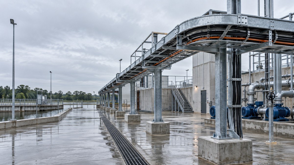
Flood resilience is increasingly part of electrical planning for water plants, ports, substations, tunnels, transport facilities, coastal industrial sites, and low-lying utility areas. Cable tray does not contain energized equipment in the same way as a switchboard or control panel, but its route directly affects whether cables remain supported, accessible, and recoverable after water enters a site.
A corrosion-resistant finish alone does not make a cable tray system flood resilient. Route elevation, support foundations, drainage, debris impact, material interfaces, cable entries, emergency-system separation, and post-event access all matter. Engineers and buyers should translate the project flood strategy into measurable tray and support requirements before the bill of quantities is released.
Start with the Project Flood Design Basis
The required flood level, freeboard, wave or flow effects, drainage assumptions, and critical operating functions should come from the civil and project design basis. Cable tray suppliers should not invent these values. Their role is to provide a system that matches the approved route elevation, support loads, environmental exposure, and installation details.
Routes should be classified by consequence. Cables serving emergency pumps, communications, fire protection, controls, or safe shutdown functions may require greater separation or a more protected route than ordinary building services. The electrical engineer should decide which circuits must remain available during an event and which can be restored afterward. The tray layout then needs to preserve those functional boundaries.
Existing sites require field verification. Drawings may not show later cable additions, altered drainage channels, raised equipment pads, new pipework, or blocked access. A route survey should record low points, penetrations, outdoor transitions, support bases, cable drops, joints, and locations where floodwater or debris could collect.
Elevate Routes and Protect Their Access
Where the project permits, elevating cable routes above the design flood level is usually more effective than relying only on coatings. The elevation must include the lowest part of the cable support system and should account for cable drops, junction interfaces, and the actual route into equipment. A high main tray offers limited benefit if its cables descend through an unprotected low point before reaching the load.
Elevation also changes installation and maintenance. Crews need safe access to covers, splices, bends, and branches. Tray routes should not block platforms, ladders, doors, crane paths, or removal zones for pumps and motors. Where elevated supports cross vehicle or maintenance routes, clearance and impact protection must be coordinated with the civil and structural teams.
Vertical transitions deserve close attention. Cables entering buildings, trenches, raised control rooms, or elevated equipment should have suitable support and bend geometry. Openings and penetrations must follow the approved water, fire, and building-envelope details. Cable tray should not be used as a substitute for a sealed penetration system.
Design Supports for Water, Debris, and Soil Conditions
A tray may remain above water while its support bases are exposed to saturation, erosion, settlement, or debris impact. The structural design should address the complete load path from tray and cables through brackets, posts, anchors, concrete pedestals, and foundations. Cable tray manufacturers can provide system information, but foundation and site loads remain a project engineering responsibility.
Supports should avoid creating pockets that trap water and contaminants. Base plates, channels, overlapping members, and horizontal surfaces need drainage and inspection access. Fasteners and hold-down clamps should match the specified corrosion system. Unreviewed substitutions can create weak interfaces even when the main tray has a robust finish.
Stormwater flow paths should be kept separate from cable routes and support foundations. A drainage channel can carry fast-moving water, silt, branches, or maintenance debris even when the surrounding yard is only shallowly flooded. Posts placed inside that flow can collect debris and transfer unexpected force to the tray. Civil drawings, finished levels, drain inlets, curb openings, and overflow routes should therefore be reviewed together with the electrical layout. Where a crossing cannot be avoided, the structural detail and inspection access need explicit project approval.
Long elevated runs may also require consideration of thermal movement, wind, seismic effects, and structural movement. Covers increase wind area and can become loose if their clamps are not suited to the exposure. The project engineer should decide where covers are necessary and how they are restrained; specifying covers everywhere can increase structural demand and reduce post-event inspection access.
Select Tray Details by Exposure and Recovery Need
| Route Condition | Primary Risk | Procurement and Design Check |
|---|---|---|
| Elevated outdoor main route | Weather, wind, long spans, support-base exposure | Load data, finish, support spacing, hold-down clamps, thermal movement, route access |
| Low building or trench transition | Water entry, sediment, inaccessible cable drops | Approved penetration detail, drainage, bend support, replaceable route section, inspection clearance |
| Coastal or contaminated flood zone | Salt or chemical residue, accelerated corrosion, material mismatch | Project-approved material system, compatible fasteners, cleanable details, coating repair and inspection plan |
| Critical emergency route | Common-cause damage and loss of essential function | Functional separation, independent supports where required, protected entries, route identification |
| Retrofit in operating facility | Unknown profiles, congested access, shutdown limitations | Field dimensions, transition fittings, temporary support plan, route-based installation kits |
Hot-dip galvanized steel may be suitable for many exposed infrastructure routes, while stainless steel, aluminum, or another project-approved material may be selected for more aggressive environments. The choice should consider the complete system, including fittings, supports, covers, splice plates, fasteners, bonding components, and contact with other metals. Material names should not replace an exposure assessment.
Plan Inspection and Recovery Before the Event
A resilient design includes a recovery plan. After flooding, qualified personnel should assess whether the tray's mechanical or electrical integrity has been affected and whether cables or connected equipment have been exposed. Water can carry silt, salts, oils, sewage, or process chemicals, so a route that appears dry later may still require cleaning, testing, repair, or replacement under the owner's procedures and equipment guidance.
The route should be inspectable without using the tray as a walkway. Access points, removable covers, route labels, photographs, and as-built drawings make the assessment faster. Low points and interfaces should be included in inspection checklists. Spare fittings and compatible hardware should be stored for critical systems, especially where the installed profile is project-specific or sourced internationally.
Designers should also consider how damaged sections can be changed while cables remain protected or while essential circuits are transferred. A transition placed in an accessible area is easier to replace than one hidden behind equipment. Route-based spare kits can include straight sections, splice plates, supports, fasteners, clamps, and approved coating-repair materials.
RFQ Checklist and Final Buying Advice
- Provide the approved flood design basis, route elevations, exposure zones, cable schedule, and critical-circuit classification.
- Define tray type, usable dimensions, support spacing, design load information, fitting radii, finish, and material interfaces.
- Identify supports, posts, crossarms, anchors, hold-down clamps, fasteners, covers, dividers, and bonding accessories in the supply boundary.
- Coordinate drainage channels, raised pedestals, penetrations, equipment entries, vehicle clearances, and maintenance access.
- Request project-required structural, material, corrosion, dimensional, and inspection documentation before production.
- Define post-event inspection, cleaning limitations, spare parts, coating repair, and replacement responsibilities.
Flood-resilient cable tray planning begins with route elevation and system function, then extends through supports, materials, drainage, access, and recovery. Buyers should resist reducing the decision to a finish comparison. A well-coordinated elevated route can protect installation access and simplify recovery, while a poorly detailed transition can leave critical cables exposed at the lowest point.
HONGFENG / Cable Tray Pro can review route drawings, tray schedules, material options, support interfaces, fittings, and export packing for infrastructure and industrial projects. Share the approved environmental and structural requirements to discuss a practical cable tray package without replacing project engineering assumptions.
Navigation
Send Us A Message
Get in touch with us
Phone