
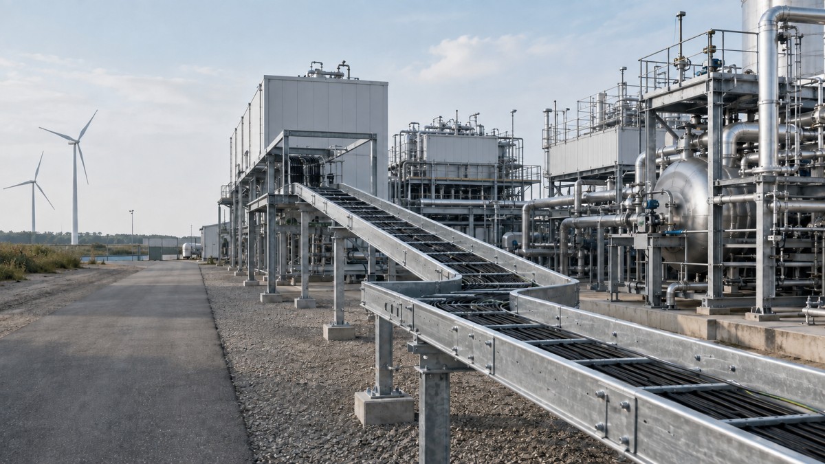
E-methanol and other Power-to-X projects connect renewable electricity, hydrogen production, carbon dioxide handling, chemical synthesis, storage, and product loading within one facility. That combination creates a cable-routing problem that is more complex than a conventional utility plant or a stand-alone electrolyzer. High-current power circuits, process instrumentation, safety systems, communications, and package-vendor cables may all cross the same pipe racks and modular interfaces.
For EPC contractors and procurement teams, the cable tray package should therefore be planned around plant areas and interfaces, not selected as a single generic product. Tray type, material, cover strategy, support arrangement, fittings, bonding provisions, and delivery sequence must support the electrical design as well as the construction plan. Early coordination reduces site-fabricated changes and helps each process package connect to the common plant infrastructure without creating inaccessible or incompatible routes.
Why Power-to-X Plants Create Complex Cable Routes
A typical e-methanol facility may include electrical substations, rectifiers, electrolyzer modules, water treatment, hydrogen compression, carbon dioxide conditioning, synthesis units, distillation, cooling systems, tank storage, fire and gas systems, and loading facilities. Each area has a different cable population and operating environment. The main power route serving the electrolyzer may need substantial capacity and ventilation, while local instrumentation routes around synthesis skids need frequent branches and careful separation from power circuits.
The physical layout can also evolve as process licensors and package vendors release information. Equipment nozzle locations, access platforms, pipe-rack elevations, modular battery limits, and hazardous-area drawings may develop at different times. A cable tray layout that is frozen too early can conflict with piping or require extra field bends. A layout released too late can delay support steel and cable installation. The practical answer is a controlled design basis with clearly identified hold points for changing interfaces.
Buyers should ask for a tray schedule by area, not only a total tonnage or list of straight lengths. The schedule should identify tray type, usable width and side-rail height, material and finish, design load basis, support assumptions, fitting families, covers, dividers, splice hardware, and any special requirements at module boundaries.
Match Tray Type to Cable Function and Access
Ladder Cable Tray for Main Power Distribution
Ladder cable tray is commonly considered for main power feeders because its open construction supports ventilation, cable entry, and inspection. It can be practical along outdoor pipe racks and between substations, rectifier buildings, compressors, and major process packages. Selection still depends on the cable load, support span, route geometry, environmental exposure, and project specification. A tray with adequate width but an unsuitable structural configuration may still perform poorly.
Perforated Tray for Control and Instrumentation
Perforated cable tray provides more continuous support for smaller cables and can suit control, instrumentation, and auxiliary circuits. Drainage, ventilation, cover requirements, and cable separation should be evaluated for each location. Where several cable systems share a route, dividers may help maintain the project-defined segregation, but a divider should not be treated as a substitute for the electrical engineer's routing and separation rules.
Trunking and Wire Mesh for Local Distribution
Cable trunking may be useful for protected local circuits inside buildings or package enclosures, while wire mesh tray can support flexible branch routing in clean, accessible indoor zones. Neither should be specified simply because it is convenient to install. Cable heat, mechanical protection, corrosion, cleaning, electromagnetic compatibility, and future access remain part of the selection decision.
Plan by Plant Area, Not by Product Name
The same tray family can require different accessories and finishes across the facility. An outdoor route from a substation may prioritize structural capacity, corrosion protection, drainage, and wind effects on covers. A synthesis-area route may prioritize process-area classification, access around valves and platforms, and compatible materials. Storage and loading areas may add weather exposure, vehicle movement, and emergency-system interfaces.
| Plant Area | Typical Routing Conditions | Procurement Focus |
|---|---|---|
| Substation and rectifier area | Heavy power cables, high route utilization, building-to-outdoor transitions | Load data, ventilation, bend radius, support spacing, bonding parts, expansion interfaces |
| Electrolyzer modules | Repeated skids, dense branches, vendor battery limits, phased installation | Standardized interfaces, short fittings, drop-outs, module connection kits, tagged delivery |
| CO2 and synthesis units | Process piping congestion, instrumentation branches, classified or controlled zones | Routing clearances, finish compatibility, instrument tray, covers only where justified, access |
| Tank farm and loading | Outdoor exposure, long runs, vehicle interfaces, safety-system cables | Corrosion class, mechanical protection, support steel, route identification, spare capacity |
| Utilities and control buildings | Mixed indoor services, frequent distribution changes, ceiling congestion | Coordinated elevations, accessible branches, trunking transitions, future route allowance |
Control Corrosion, Safety, and Material Interfaces
Finish selection should reflect actual exposure at each route. Hot-dip galvanized steel may be appropriate for many outdoor industrial areas when specified and manufactured correctly. Stainless steel or another project-approved material may be required in more aggressive zones. Indoor dry areas may permit a different finish. The tray body, fittings, covers, supports, splice plates, hold-down clamps, fasteners, and bonding components should be reviewed as a complete material system.
Material transitions deserve special attention. Unreviewed contact between dissimilar metals can create corrosion concerns, especially where moisture or process contamination is present. Cut edges, field-drilled holes, damaged coatings, drainage points, and trapped debris can also determine real service performance. The RFQ should define who supplies repair materials and what site treatment procedure applies.
Cable tray is only one part of the electrical installation. Hazardous-area classification, cable type, gland selection, equipment protection, grounding and bonding, fire protection, and emergency routing must follow the approved project design and applicable local requirements. Buyers should avoid claims that a tray material alone makes an installation suitable for a hazardous location.
Manage Modular Interfaces and Construction Sequence
Power-to-X facilities often use modular equipment packages. The module fabricator may install tray within the skid while the EPC contractor supplies the interconnecting plant routes. Problems arise when the two packages use different tray profiles, widths, rung spacing, side-rail shapes, finishes, or bolt patterns. Even when both products are described as galvanized ladder tray, a direct connection may not be possible without a transition piece.
Each module battery limit should therefore have an interface drawing showing tray elevation, direction, usable dimensions, material, expected cable load, support responsibility, and connection detail. Adjustable field joints can absorb small tolerances, but they should not be used to conceal major coordination errors. Standardizing a limited set of interface sizes reduces special fabrication and simplifies spare-part planning.
Delivery should follow the installation sequence. Route-based packing and durable item tags help crews identify straight sections, fittings, covers, and supports for each work front. Critical fittings at the start of a cable pull should not be buried behind later-area materials. For overseas projects, packing lists should connect supplier item codes to the EPC tray schedule so shortages can be identified before containers arrive on site.
RFQ Checklist for E-Methanol Cable Tray Packages
- Issue the latest tray layout, area classification information, cable schedule, load basis, and route-specific finish requirements.
- Define usable tray width, side-rail height, straight-section length, rung spacing, fitting radius, and dimensional tolerances.
- List every fitting, reducer, riser, tee, cross, cover, divider, drop-out, splice plate, fastener, clamp, and bonding accessory.
- Separate indoor, outdoor, coastal, chemical-exposure, and other special areas instead of applying one finish to the entire project.
- Confirm module battery-limit connections and identify responsibility for transition pieces and local support steel.
- Request structural and material documentation required by the project specification without assuming thickness alone proves capacity.
- Define inspection, marking, packing, preservation, document, and phased-delivery requirements before purchase order placement.
Final Buying Advice
The best cable tray package for an e-methanol plant is not the one with the fewest product variations. It is the one that provides controlled interfaces across power conversion, process modules, outdoor pipe racks, storage, and buildings while remaining practical to install and maintain. Freeze standard components early, but keep engineered allowances for package changes, construction tolerances, and future expansion.
HONGFENG / Cable Tray Pro can review tray schedules, route conditions, fitting lists, material options, and export packing requirements for Power-to-X and other industrial projects. Share the available drawings and procurement specification to discuss a practical, project-specific cable tray package.
Navigation
Send Us A Message
Get in touch with us
Phone