
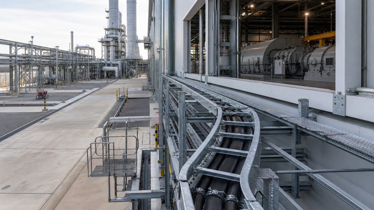
A combined-cycle power plant brings several electrical environments into one project. The gas turbine building, heat recovery steam generator (HRSG), steam turbine area, cooling system, water treatment plant, outdoor pipe racks, workshops, and control rooms do not place the same demands on a cable tray system. A tray specification that works inside a clean electrical room may be unsuitable beside hot process equipment or on an exposed utility rack.
For engineering and procurement teams, the practical objective is not simply to order tray lengths. It is to define a coordinated cable support system with the right tray type, material, load capacity, fittings, covers, supports, bonding provisions, and installation access for every plant zone. Early decisions also need to account for cable pulling, equipment maintenance, future circuits, and interfaces between civil, structural, mechanical, and electrical packages.
Start with Plant Zones and Cable Functions
Cable tray selection should begin with the route environment and the cables it must carry. Main generator, transformer, auxiliary transformer, large motor, and switchgear feeders can create heavy cable groups that require strong ladder tray and carefully designed supports. Instrumentation, control, communication, and monitoring circuits generally use smaller cables and may benefit from perforated tray, cable trunking, or a dedicated tier on a multi-level rack.
The turbine building often contains long routes around equipment skids, crane zones, access platforms, and ventilation systems. The HRSG area introduces outdoor exposure, elevated ambient temperatures near equipment, vertical changes, and dense structural steel. Cooling-water and water-treatment areas may expose trays to moisture and chemical cleaning activities. Control and electrical rooms are cleaner, but they still require disciplined separation, entry details, and future capacity.
A useful route schedule identifies the area, cable service, tray type, nominal width and side-rail height, material and finish, expected cable load, support concept, cover requirement, and special interfaces. This schedule gives bidders a common basis and reduces substitutions based only on nominal dimensions.
Match Cable Tray Type to the Duty
Ladder Cable Tray for Power Routes
Ladder cable tray is commonly evaluated for large power and motor feeder routes because its side rails and rungs provide mechanical support while keeping cables accessible and ventilated. It is well suited to long straight runs on turbine-building steelwork and outdoor utility racks when the selected rail profile, rung spacing, support span, and fittings are verified against the project load case.
Perforated Tray for Control and Auxiliary Circuits
Perforated tray gives more continuous support to smaller control, auxiliary, and instrumentation cables. Openings permit drainage and some ventilation, while the tray base helps organize compact cable groups. Where project requirements call for covers, buyers should define the cover type, fastening method, ventilation approach, and access frequency instead of assuming that a cover is included.
Trunking for Local Protection
Cable trunking or trough-style systems can be useful for local branches, panel approaches, and smaller cable groups requiring additional physical protection. Enclosed routes need attention to cable entry, drainage, heat, bend space, and maintenance access. They should be applied selectively rather than used as a default replacement for an open tray system.
Choose Material and Finish by Exposure
A combined-cycle plant can include air-conditioned rooms, humid utility buildings, open-sided structures, cooling-tower zones, and outdoor routes exposed to rain and industrial contaminants. Material selection therefore needs an area-by-area corrosion review. The tray body, splice plates, covers, brackets, fasteners, and hold-down hardware should be treated as one system.
| Plant Area | Typical Concern | Procurement Check |
|---|---|---|
| Electrical and control rooms | Dry indoor service, dense cable entries, future circuits | Confirm project-approved finish, cable separation, drop-outs, and spare capacity. |
| Turbine and HRSG structures | Outdoor exposure, heat sources, vertical changes, vibration | Verify hot-dip galvanized or other approved finish, support details, clearances, and fitting strength. |
| Cooling and water-treatment areas | Moisture, washdown, treatment chemicals, condensation | Review corrosion class, drainage, compatible fasteners, and the complete support system. |
| Outdoor pipe racks | Weather, sunlight, long runs, structural movement | Coordinate covers, expansion details, drainage, support spacing, and route access. |
Hot-dip galvanized steel is often considered for outdoor industrial routes because it combines mechanical practicality with robust corrosion protection. However, the buyer should confirm whether galvanizing is applied after fabrication, how threads and cut areas are treated, and whether fittings and supports receive a compatible finish. Stainless steel may be appropriate in particularly corrosive plant zones, but the grade and all associated hardware must match the project specification.
Design Supports for Load, Heat, and Vibration
Tray capacity cannot be separated from support design. The support span used in the supplier's load data must match the proposed site arrangement, and concentrated loads near vertical risers, bends, tees, cable drops, and heavy cable groups need specific review. A wide tray with a strong side rail can still perform poorly if brackets twist, anchors are unsuitable, or supports are placed without regard to fitting locations.
Power plants also contain rotating equipment, thermal movement, and structures that may vibrate during operation. Tray routes should avoid unnecessary attachment to vibrating equipment and preserve the clearances required for inspection and maintenance. Flexible interfaces or independently supported transitions may be necessary where a route crosses between structures or equipment packages. These details should be resolved by the project engineer rather than improvised during installation.
Heat sources deserve similar attention. Cable tray should not be routed simply through the shortest available corridor if that corridor is close to hot surfaces or blocks ventilation around equipment. The electrical design must account for the actual ambient condition, cable grouping, and equipment manufacturer requirements. Covers can protect cables from falling debris or weather, but they can also affect heat dissipation and access, so their use should be defined by location.
Coordinate Fittings, Access, and Future Changes
A plant tray package needs more than straight sections. Horizontal and vertical bends, tees, crosses, reducers, risers, splice plates, barrier strips, cover clamps, hold-down clamps, drop-out plates, and support channels must match the tray family. Large power cables may require generous bend geometry and space for pulling equipment. Fittings should be supported according to the approved design, not left to bridge long gaps between straight-run supports.
Maintenance access is especially important around turbines, pumps, valves, and crane routes. Tray should not obstruct removal paths or force technicians to work over hot equipment. A route that appears compact on a model can become difficult to cable if there is no space for rollers, pulling personnel, or controlled cable entry. Constructability reviews should therefore include the sequence of structural steel, piping, tray support, tray installation, and cable pulling.
Future capacity should be deliberate. Instead of applying one arbitrary spare percentage to every route, teams can identify likely future generators, pumps, analyzers, package units, and control upgrades. Spare width, additional tiers, or reserved support positions can then be assigned where expansion is realistic. This gives procurement a clearer quantity basis and avoids buying oversized tray for routes that will never change.
Combined-Cycle Cable Tray RFQ Checklist
- Issue a route or area schedule showing tray type, width, side-rail height, material, finish, and cover requirement.
- State the design cable load and the support span associated with the required tray capacity.
- Separate power, control, instrumentation, communication, and safety-related services as required by the approved design.
- Include the complete fitting, splice, barrier, cover, clamp, fastener, and support scope.
- Identify outdoor, wet, hot, vibrating, or corrosive zones requiring special review.
- Confirm bonding continuity provisions and any project-specific grounding accessories.
- Request dimensional drawings, load data, finish documentation, packing lists, and installation information with the bid.
- Check that packing and identification preserve installation sequence for international delivery.
Final Buying Advice
The strongest combined-cycle cable tray specification connects electrical loading with the real plant environment. Buyers should compare suppliers on system completeness, load data, material compatibility, fitting quality, dimensional consistency, and documentation rather than on tray weight or unit price alone. Route schedules and a clear bill of materials also make technical bid comparisons more reliable.
HONGFENG / Cable Tray Pro can review project tray schedules, drawings, environmental requirements, and accessory lists to help contractors and EPC buyers prepare a coordinated cable tray package. Final selection, support design, and installation should always follow the approved project specification, equipment requirements, and applicable local rules.
Navigation
Send Us A Message
Get in touch with us
Phone