
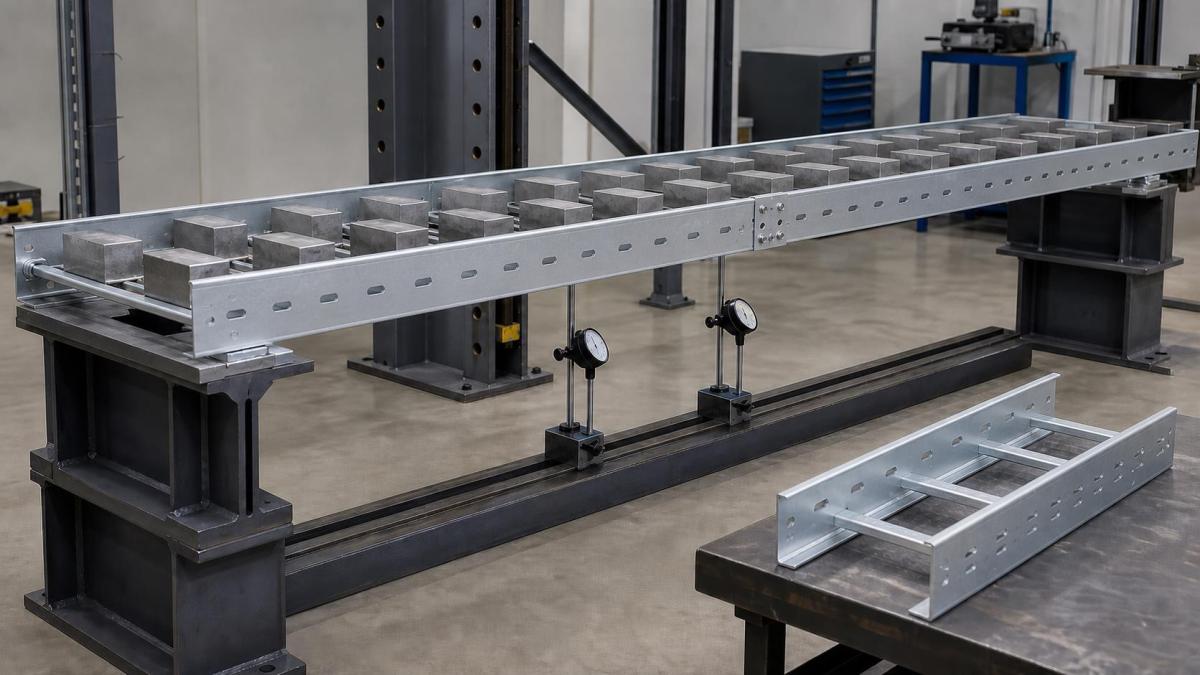
Cable tray buyers often compare quotations by material thickness because it is easy to list and measure. Thickness matters, but it does not define load capacity by itself. Side-rail shape, height, return flanges, rung construction, tray width, material strength, support span, splice position, and manufacturing quality all influence structural performance. EPC contractors should compare verified load data for the complete system instead of assuming that the thickest tray is automatically the strongest or most economical.
Why Thickness Is Only One Input
A flat strip and a formed side rail can use the same sheet thickness but have very different stiffness. Bends, returns, beads, and section depth move material away from the neutral axis and change how the rail resists bending. Two trays with identical width and thickness can therefore carry different loads.
Material grade also matters. Yield strength and elastic properties affect permanent deformation and allowable load. A specification that states only steel cable tray, 2.0 mm thick leaves the supplier without the full structural basis needed for a comparable offer.
Load Capacity Comparison Table
| Specification Item | Why Thickness Alone Is Not Enough | What Buyers Should Request |
|---|---|---|
| Side-rail profile | Folded geometry, return edges, and rail height strongly affect stiffness. | Section drawing, side height, rail profile, material grade, and thickness tolerance. |
| Tray width and support span | The same thickness can perform differently at different widths and spans. | Rated load table for each width and support span used in the project. |
| Rungs and perforations | Rung shape, spacing, weld quality, and hole pattern affect load distribution. | Rung spacing, rung profile, perforation layout, weld details, and inspection criteria. |
| Splice position and deflection | Joints near high bending locations can reduce practical route performance. | Test arrangement, splice details, deflection limit, and installation guidance. |
When comparing quotations, buyers should avoid treating tray thickness as a substitute for test data. A heavier sheet may still perform poorly if the profile is shallow, the rungs are weak, the support span is long, or the splice detail is not suitable for the route. A technically valid comparison needs load tables and a clear description of the test or calculation basis.
Side-Rail Height and Profile
For cable ladder and many tray systems, side rails carry much of the longitudinal bending load. Increasing side-rail height or using a more efficient formed profile can increase stiffness without a proportional increase in thickness. Return flanges, ribs, and multi-bend profiles can also resist local buckling and twisting.
Buyers should request a section drawing showing overall height, usable cable depth, flange dimensions, material thickness, and connection-hole arrangement. Usable depth may be less than nominal side height, particularly when covers, dividers, or internal flanges occupy space.
Tray Width Changes the Structural Demand
A wider tray can hold more cables and has a larger transverse span between side rails. Bottom panels or rungs must support cable weight across that width. The same side rail used on a narrow and wide tray does not guarantee identical performance for every loading condition.
Perforated tray bottoms need enough stiffness to limit oil-canning or local deformation. Cable ladder rungs require suitable profile, spacing, and attachment. Wide heavy-duty ladders may need stronger rungs even when side rails remain unchanged.
Rung Spacing and Attachment
Rung spacing affects cable support, cable cleat installation, and local rung load. Large power cables may need closer support or specific cleat positions. The rung itself must resist cable weight and any approved concentrated load, while the rung-to-rail connection transfers that load into the side rails.
Welded, swaged, bolted, or mechanically locked rungs can perform differently. The construction used in the load data should match the product being ordered. A buyer should not combine a tested side rail with a different rung or attachment and assume the original rating remains valid.
Support Span Has a Major Effect
Load capacity depends strongly on the distance between supports. Increasing the span raises bending demand and deflection. A tray rated for one support spacing cannot be assigned the same allowable load at a longer span without verified data.
The project should state the required distributed load and support spacing together. It should also define whether the load includes tray self-weight, covers, dividers, cables, and future allowance. Comparing supplier tables is only meaningful when the span, test arrangement, and acceptance basis are the same.
Deflection and Permanent Set
Structural acceptance is not only about avoiding collapse. Excessive deflection can change appearance, reduce clearance, stress cables, disturb covers, or create water collection points. Project specifications may limit deflection or permanent set after unloading.
Load tables should identify the test method, support condition, splice position, load distribution, and reported criterion. A high ultimate test load does not automatically provide an appropriate working load. Buyers need the allowable or recommended load under the stated conditions.
Splice Joints and Support Location
Splice plates connect tray sections mechanically, but joint stiffness can differ from the continuous side rail. Load performance may change depending on whether the splice is near a support or near midspan. The manufacturer's test arrangement and installation instructions should define the acceptable joint location.
Standard splice plates, heavy-duty connectors, adjustable splices, and expansion connectors are not interchangeable. Expansion joints permit movement and require a coordinated fixed-point and guide-support arrangement. A movement connector should not be placed where a rigid load-transfer joint is required.
Fittings Need Their Own Support Review
Horizontal bends, vertical bends, tees, crosses, reducers, and risers interrupt straight side rails and redistribute load. They may need supports at specific locations. A straight-section load rating does not justify leaving a large tee or bend cantilevered.
Heavy cable drops and vertical transitions also introduce concentrated forces. The route drawing should show additional supports, cable cleats, and equipment interface details. These items belong in the BOQ and support schedule.
Material and Finish Can Affect Dimensions
Hot-dip galvanizing adds a zinc coating after fabrication and can influence hole fit, moving joints, or local straightness if the product is poorly controlled. Powder coating adds another layer at joints and cover interfaces. Stainless steel and aluminum use different material properties from carbon steel.
Load data should apply to the ordered material and construction. When several finishes use the same geometry, the supplier should identify whether the rating is shared, adjusted, or separately verified. The finish specification should also define coating repair at field cuts without encouraging unapproved structural modification.
How Buyers Should Compare Quotations
A useful technical comparison places each supplier's proposed tray beside the project load requirement and support span. Record side-rail profile and height, width, thickness, material grade, rung or bottom construction, splice arrangement, finish, and applicable test data. Differences become visible without reducing the decision to kilograms per meter.
Weight can help check commercial consistency and shipping, but it is not a substitute for performance data. An efficiently formed section may use less material while meeting the required load. Conversely, extra thickness in a poorly shaped or weakly connected system may add cost without solving the governing condition.
RFQ Checklist for Load-Capable Cable Tray
- Tray type, width, side height, usable depth, and standard section length
- Required distributed load, cable weight, future allowance, and support span
- Any concentrated load and its position
- Material grade, base metal thickness, and surface finish
- Side-rail section drawing, rung profile, rung spacing, and attachment method
- Splice plate type, fasteners, joint position, and expansion requirements
- Deflection or permanent-set criterion where specified
- Load test standard, test arrangement, report, and applicable product range
- Additional supports for fittings, branches, risers, and cable drops
Work With Hongfeng Electric
Hongfeng Electric can review cable tray dimensions, cable loads, support spacing, fitting details, material, finish, and accessory scope for project quotations. Send the route schedule, required load and span, tray widths and heights, material grade, fitting list, cover requirement, and requested test documents. HF Cable Tray can then propose a defined section and support package instead of relying on thickness alone.
Navigation
Send Us A Message
Get in touch with us
Phone