
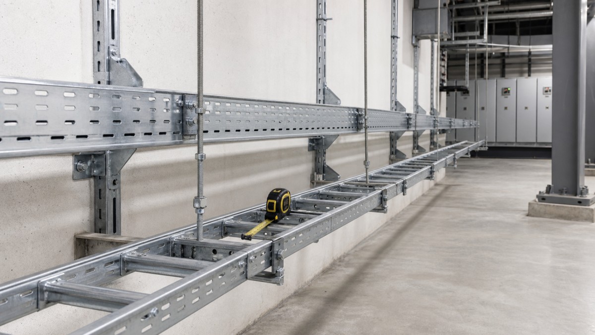
Galvanized cable tray route with visible supports and load spacing check in an industrial utility corridor
Support spacing and load capacity are two of the most common weak points in cable tray RFQs. A buyer may request the right tray width and finish, but if cable weight, span length, support method, fittings, and installation conditions are not reviewed together, the system can become difficult to install or maintain. For EPC contractors, electrical installers, and project procurement teams, these checks should happen before the quotation is finalized.
The goal is not to turn every buyer into a structural engineer. The goal is to give the supplier enough information to recommend a cable tray system that fits the project drawings, cable schedule, and installation environment. Clear RFQ information reduces guesswork and helps avoid missing supports, wrong tray thickness, unsuitable accessories, and site changes.
What Load Capacity Means in a Cable Tray Order
Cable tray load capacity is not only the weight of the tray itself. It includes the installed cable weight, planned future cable allowance, fittings, covers, possible environmental loads, and the spacing between supports. A ladder cable tray on short spans may perform very differently from the same tray on a long unsupported route.
Buyers should avoid asking only for a tray size such as 300 mm wide or 600 mm wide. The supplier also needs to know the side height, material thickness, tray type, support spacing, cable load, route length, and whether covers or dividers will be installed. If the project has a specified standard or test requirement, include it in the RFQ rather than assuming all suppliers use the same basis.
Support Spacing Should Match the Route
Support spacing is often copied from a previous project, but different routes may need different spacing. A light low-voltage route in a dry indoor corridor is not the same as a heavy power route in an outdoor pipe rack. Wall-mounted brackets, trapeze supports, cantilever arms, floor stands, and strut systems all affect how the cable tray behaves under load.
Support locations should also avoid tray joints where possible unless the project design allows it. Splice plates, expansion joints, vertical bends, tees, reducers, and equipment transitions may need additional support. If the RFQ includes a route drawing, mark any long spans, restricted mounting points, vibration areas, seismic requirements, and outdoor sections.
Choosing Tray Types for Different Load Conditions
Product type selection should follow cable weight, route length, cable pulling method, protection needs, and maintenance access.
- Ladder cable tray: Often preferred for heavier power cables, long runs, utility corridors, and pipe racks because it provides ventilation and easier cable pulling access.
- Perforated cable tray: Suitable for smaller power cables, branch circuits, control routes, and areas where cables need more continuous bottom support.
- Wire mesh cable tray: Useful for lighter data, communication, automation, and low-voltage routes where flexibility and easy field modification are important.
- Cable trunking: Suitable for protected control, communication, or building service routes where enclosed protection and a tidy appearance matter.
For heavy routes, the buyer should confirm tray thickness, side rail height, rung design, perforation pattern, and support method. For lighter routes, it is still important to specify cable fill and future spare capacity so the system is not overloaded after later upgrades.
Material and Finish Considerations
Load performance and corrosion protection should be specified together. A strong tray body with weak fasteners or mismatched brackets can still become a problem. For protected indoor projects, pre-galvanized or galvanized steel cable tray may be suitable. For outdoor routes, pipe racks, coastal facilities, substations, or industrial service areas, hot-dip galvanized cable tray is often requested. Stainless steel may be needed for chemical, food, coastal, or high-humidity environments.
When covers are used, remember that they add weight and can change support requirements. Covers should be included in the load discussion, along with cover clamps, hold-down parts, and any wind exposure on outdoor routes. If the project uses powder coating or special coating, ask how cut edges, drilled holes, and field modifications should be repaired.
Fittings and Accessories Affect Support Design
Straight cable tray sections are only part of the system. Bends, tees, crosses, reducers, risers, drop-outs, covers, splice plates, grounding accessories, and support hardware must be compatible with the selected tray. These items also affect installation strength and maintenance access.
Vertical bends and tees often need careful support near route changes. Wide horizontal bends may require extra consideration for cable pulling and cable weight distribution. Covers may need hold-down clamps in outdoor or vibration areas. Bonding jumpers, grounding washers, or other grounding-related parts should be included when required by the project specification and local electrical code.
Common RFQ Gaps That Create Site Problems
- Tray width is specified, but side height, thickness, or load class is missing.
- Support spacing is not provided, so the supplier cannot verify load assumptions.
- Cable schedule is unavailable, making it difficult to estimate cable weight and spare capacity.
- Outdoor routes are quoted without covers, hold-down clamps, grounding details, or finish repair method.
- Fittings are counted separately from straight tray, causing missing bends or reducers at site.
- Fasteners, splice plates, brackets, and strut channels are not matched to the tray finish.
RFQ Checklist
- Project type, route drawings, indoor or outdoor environment, and installation restrictions.
- Cable tray type, width, side height, material thickness, and required straight lengths.
- Cable schedule, estimated cable weight, future cable allowance, and any load standard requested.
- Support spacing, support type, mounting surface, and long-span or vibration zones.
- Material and surface finish, including hot-dip galvanized, pre-galvanized, stainless steel, or coating requirements.
- Fittings, covers, splice plates, grounding accessories, fasteners, and packing list by route.
- Engineering drawings, custom sizes, OEM/ODM requirements, delivery batch plan, and inspection documents.
Work With CableTrayPro
CableTrayPro can review your tray schedule, cable load notes, support concept, drawings, and finish requirements before quotation. Our team can help select ladder cable tray, perforated cable tray, wire mesh cable tray, cable trunking, strut channel, brackets, covers, and fittings for project supply. Send your RFQ package for specification support, custom sizes, bulk ordering, and a fast quotation.
Navigation
Send Us A Message
Get in touch with us
Phone