
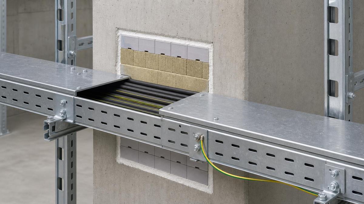
When a cable tray passes through a fire-rated wall or floor, the tray layout and the fire-stopping system become one coordinated interface. The opening must accommodate the tray, installed cables, bonding arrangements, and an approved penetration seal without creating an impractical installation sequence. If these requirements are considered only after the tray has been delivered, the contractor may face oversized openings, unsupported fittings, difficult inspections, or costly site changes.
This subject is different from specifying a coated or enclosed cable tray. Fire stopping is intended to maintain the required performance of the wall or floor penetration using a tested and project-approved system. The cable tray itself, its cover, and any protective coating do not replace the penetration design.
Start With the Fire Compartment Drawing
The cable tray routing team should identify every fire-rated barrier before issuing the tray bill of quantities. For each penetration, record the barrier type and thickness, required fire performance, opening size, tray type and dimensions, cable population, and the fire-stopping system accepted for the project. The fire engineer or responsible design authority should approve the final arrangement.
Penetrations through concrete walls, blockwork, lightweight partitions, and concrete floors can require different tested systems. A detail accepted for a solid wall should not be assumed to work in every other construction. The selected system also needs to match the orientation of the opening and the services passing through it.
Coordinate the Opening With the Cable Tray
The builder's opening should not be sized from the tray's nominal width alone. Side rails, flanges, covers, cable cleats, dividers, and installation tolerances all occupy space. The fire-stop installer also needs enough working clearance to place and inspect the specified sealing materials.
Tray fittings should be kept away from the penetration unless the approved detail specifically allows them. A bend, reducer, or splice plate positioned inside the wall can restrict access and complicate sealing. Straight tray sections on both sides generally provide a clearer interface, but the exact arrangement must follow the approved design.
Floor penetrations require additional coordination for edge protection, water ingress during construction, falling-object control, and the final load around the opening. Temporary protection should not damage the finished fire-stop system or obstruct later inspection.
Account for Cable Fill and Future Changes
A penetration that is packed tightly on the first installation leaves little room for correct sealing or later additions. The design should define both the initial cable population and the expected future capacity. Spare capacity needs to be part of the approved penetration system, not simply an empty gap left around the cables.
Project teams may use approved modules, sleeves, blocks, boards, mortars, sealants, wraps, or other tested components depending on the barrier and service configuration. Product selection belongs with the fire-stopping designer and project approval process. Cable tray buyers should avoid prescribing an unverified material combination in the tray purchase order.
When future cables are likely, the specification should state how the seal can be reopened and reinstated. It should also define responsibility for updating penetration records after modifications. A maintainable system reduces the risk of uncontrolled gaps appearing during plant expansion.
Support the Route on Both Sides
The wall or floor penetration should not be used as a tray support. Supports near the barrier need to hold the tray and cable load independently while leaving enough access for fire-stop installation and inspection. Their location should be checked against the approved penetration detail, tray manufacturer's loading information, and structural fixing requirements.
Vertical floor openings need a defined cable restraint strategy. The cable weight should be carried by suitable cleats or clamps and support steel, not by the sealing material. The tray, support frame, and cable restraint design should be coordinated so that no concentrated load is transferred into the fire stop.
Where movement joints, vibration, or thermal movement occur near a barrier, the design team should confirm whether the penetration system can accommodate the expected movement. Moving a tray route by a small distance at the drawing stage can be easier than resolving an unsuitable interface during installation.
Confirm Continuity, Bonding, and Covers
A fire-rated barrier may interrupt the normal arrangement of tray splice plates or bonding conductors. The electrical designer should confirm how metallic continuity and protective bonding will be maintained across the penetration. Any bonding jumper should remain accessible where inspection or testing is required and must be compatible with the tray material.
If tray covers are required, the detail should show whether the cover continues through the opening, stops before the wall, or changes type. Cover clamps should not conflict with the sealing zone. Enclosed cable trunking and multi-compartment trunking may require separate penetration details because internal compartments and lids can affect the approved configuration.
Define the Interface in the Procurement Package
The cable tray supplier, fire-stop subcontractor, builder, electrical installer, and fire engineer may each control part of the same opening. A responsibility schedule prevents missing items. It should state who supplies sleeves or frames, who forms the opening, who installs supports, who applies the seal, and who records and inspects the completed penetration.
Tray fabrication drawings should mark fire barriers and identify any special straight lengths or support positions. The fire-stop submittal should reference the actual tray and cable arrangement. When several tray tiers pass through one opening, the detail must show clear separation and access around every tier.
RFQ Checklist for Penetration Areas
- Barrier location, construction, thickness, orientation, and required fire performance
- Approved or proposed tested fire-stopping system and design responsibility
- Tray type, width, side height, material, finish, cover, and divider arrangement
- Initial cable quantity, cable outside diameters, cable groups, and future capacity
- Opening dimensions, sleeves or frames, clearances, and installation sequence
- Support positions, bracket details, vertical cable restraints, and structural fixings
- Splice locations, bonding jumpers, grounding connections, and inspection access
- Penetration identification, records, inspection documents, and modification procedure
Work With Hongfeng Electric
Hongfeng Electric can supply coordinated cable tray and cable ladder components for routes that cross fire-rated walls and floors, including special lengths, supports, covers, dividers, fittings, splice plates, and bonding accessories. Send the tray layout, penetration schedule, approved fire-stop constraints, cable data, and support details with the RFQ. The resulting quotation can then reflect the actual interface while leaving fire-stopping design and approval with the responsible project specialists.
Navigation
Send Us A Message
Get in touch with us
Phone