
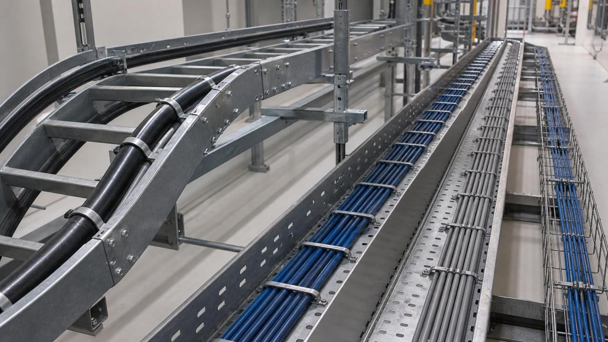
Cable tray width is often estimated early from a cable list and then repeated across drawings and purchase schedules. That shortcut can hide three different design questions: whether the cables physically fit, whether incompatible cable groups are properly separated, and whether the route can accept planned future circuits. A tray that appears adequate by nominal area may become congested at bends, tees, risers, and equipment entries.
For EPC contractors and project buyers, fill planning should connect cable data with tray geometry, route layout, loading, ventilation, and accessories. The goal is not to select the widest tray available. It is to establish a buildable arrangement that can be quoted, installed, inspected, and expanded without unnecessary tray tiers or site modifications.
Build the Calculation From Cable Data
A dependable tray schedule starts with more than cable quantity. The design team should provide cable outside diameter, weight per metre, minimum bending radius, circuit function, voltage or signal category, termination destination, and any project rules for grouping or separation. Large power cables also need a defined laying arrangement and fixing method.
Outside diameter determines occupied width, but manufacturing tolerances, cable spacing, cleats, and installation access also matter. Cable weight affects the tray and support load. Bending radius controls the space required at horizontal and vertical fittings. These inputs should be kept consistent between the cable schedule, routing model, and supplier RFQ.
Use the Tray's Usable Space
Nominal tray width is not always the same as usable cable width. Side rails, inward flanges, corrugations, divider bases, splice hardware, and cover arrangements can reduce the clear space. Buyers should request the supplier's internal dimensions and construction drawing when fill is close to the project limit.
Cable ladder is commonly selected for larger power cables because it offers ventilation and accessible fixing points. Perforated cable tray provides more continuous support for smaller power and control cables. Wire mesh tray can suit light data and communication routes where flexible branch changes are expected. Cable trunking offers enclosure but requires careful review of internal compartments, heat, and access.
The selected tray depth should keep cables contained without making installation and inspection difficult. Deep side rails can improve containment in some routes, yet they can also restrict access to lower cable layers. The cable arrangement should be reviewed as an installed section rather than as a simple area calculation.
Separate Power, Control, Instrumentation, and Data
Segregation requirements come from the project's electrical, control, communication, and electromagnetic compatibility design. Power circuits, variable-frequency drive cables, control wiring, instrumentation, fire alarm, and data cables may need separate trays, physical distance, or metallic dividers. The correct method depends on circuit characteristics and project requirements.
A divider is not free space. It occupies part of the tray width and requires fixing hardware, continuity details where applicable, and compatible fittings at bends and tees. If several compartments are needed, a purpose-designed multi-compartment trunking system or separate tray tiers may be easier to install and maintain than multiple field-fitted dividers.
Route crossings also need attention. Separation shown along straight runs can disappear at a crowded riser or panel entry. Drawings should identify how cable groups pass through bends, reducers, drop-outs, and penetrations without creating sharp transitions or uncontrolled mixing.
Define Spare Capacity as a Physical Arrangement
A statement such as reserve space for future cables is not enough for procurement. The design should identify where the spare capacity sits, which cable class may use it, and whether future installation can occur without removing live cables. A percentage target can support planning, but the layout must still be checked using expected cable sizes and routes.
Future capacity may be provided through an unused lane, an empty compartment, spare tray width, or a separate tray tier. The right choice depends on expansion certainty, access, load, and segregation. In an operating plant, a clearly defined spare lane can be more useful than small gaps distributed between existing cables.
Buyers should also confirm whether the support structure can carry the future cable load. Reserving geometric space without reserving tray and bracket capacity creates a later reinforcement problem. The tray, splice joints, cantilever arms, trapeze frames, strut channels, anchors, and structural attachments should be checked for the design loading condition.
Check Bends, Tees, Risers, and Covers
Congestion usually appears first at fittings. A wide straight tray may feed into a bend with an unsuitable radius, a tee with limited branching space, or a reducer that forces cables to cross. The route review should compare cable bend radii with fitting geometry and show how each cable group enters and leaves the fitting.
Vertical risers require cable cleats or clamps selected for cable size, weight, and project criteria. The fixing arrangement consumes space and may change the required tray width. At the top and bottom of a riser, support positions and vertical bends should be coordinated with cable pulling and termination access.
Covers may be required for sunlight, falling debris, weather, or mechanical protection. They can also change heat dissipation and access. The RFQ should identify cover type, ventilation requirements, hold-down clips, outdoor wind considerations, and whether covers continue through fittings.
Turn the Design Into a Purchasable Schedule
The bill of quantities should separate tray types and dimensions while keeping accessories linked to their routes. Listing only total metres of straight tray leaves the supplier unable to verify reducers, dividers, cover clips, splice plates, supports, or bonding parts. Tagging routes or drawing zones makes quotation review and staged packing more accurate.
Project teams should ask for dimensional drawings and load information for the proposed system. Any substitution in material thickness, rung spacing, side-rail profile, or fitting construction should be checked against the cable arrangement and support design before approval.
RFQ Checklist for Fill and Segregation Planning
- Cable schedule with quantity, outside diameter, weight, function, and bend radius
- Required segregation between power, control, instrumentation, and data circuits
- Tray type, clear internal width, side height, thickness, material, and finish
- Initial cable arrangement and physically defined future spare capacity
- Route load, future load, support spacing, brackets, channels, and anchors
- Dividers, cable cleats, drop-outs, covers, bonding accessories, and fasteners
- Bends, tees, crosses, reducers, risers, and equipment entry dimensions
- Layout drawings, route tags, packing sequence, inspection needs, and delivery stages
Work With Hongfeng Electric
Hongfeng Electric can review cable schedules and tray layouts for cable ladder, perforated cable tray, wire mesh tray, cable trunking, supports, dividers, covers, fittings, and bonding accessories. Include cable dimensions and weights, segregation rules, future capacity, route drawings, finish requirements, and delivery stages in the inquiry. This allows the quotation to reflect usable tray space and a complete accessory scope rather than nominal straight-section quantities alone.
Navigation
Send Us A Message
Get in touch with us
Phone