
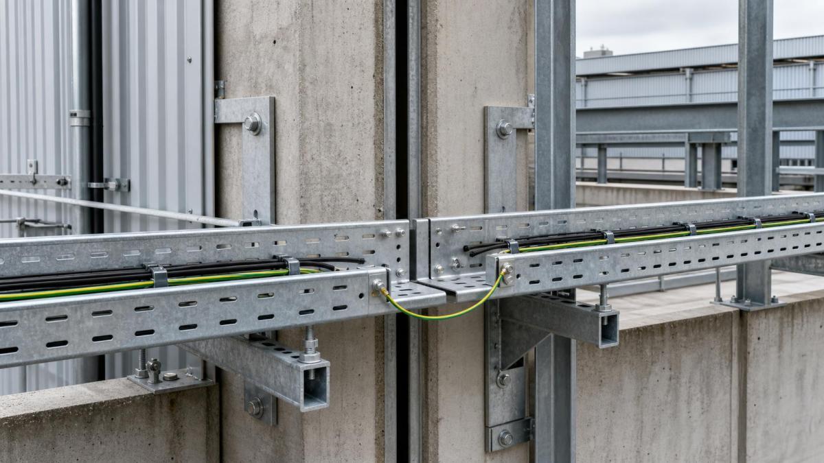
Long cable tray routes can cross building sections, outdoor structures, roofs, process areas, and equipment foundations that do not experience the same temperature or movement conditions. A continuous metallic route may appear simple in a layout, yet thermal expansion, contraction, building movement, and equipment vibration can place stress on splice joints, supports, covers, and connected cables.
Expansion movement should therefore be considered during cable tray design and purchasing. The objective is to define where movement is expected, how the tray system will accommodate it, and which accessories must remain compatible with the selected material and finish. This is especially useful for EPC packages with long outdoor routes or multiple building interfaces.
Identify Where Movement Can Occur
Movement is not limited to a hot outdoor route. It can also occur where a tray crosses a structural separation, connects two buildings, approaches vibrating equipment, changes from indoor to outdoor service, or is fixed to supports with different stiffness. Roof-mounted routes may see large temperature changes, while shaded indoor runs may remain relatively stable.
The design team should mark movement zones on the cable tray layout and structural drawings. Each zone should identify the direction of expected movement, the fixed and sliding support concept, the tray width and side height, and the cable arrangement through the transition. The approved detail should remain consistent between the tray drawing, support drawing, and construction package.
Separate Fixed Points From Sliding Points
A tray route needs a controlled support strategy. If every support clamps the tray rigidly, movement can accumulate at a splice or fitting. If too many supports are left free to slide, the route may shift during cable installation or lose alignment. The final arrangement should be developed by the responsible design team using the project movement criteria and the supplier's component information.
Typical coordination decisions include the location of fixed supports, the direction of permitted sliding, the treatment of splice connections, and the way covers move with the tray. These decisions should not be left to installers without a drawing detail. A clear support schedule also helps the buyer distinguish standard brackets from movement-specific components.
Choose Accessories That Allow Continuity
Expansion details may require special splice plates, slotted connections, sliding hardware, cover joints, flexible bonding links, or additional support parts. The exact combination depends on tray construction, material, movement, and project requirements. A standard straight splice plate should not be assumed to provide the required movement range.
Bonding and electrical continuity need separate attention. A movement joint can interrupt the normal metal-to-metal path at a splice. The electrical design should define whether a flexible bonding jumper or another approved continuity arrangement is required. The selected bonding part should allow movement without placing tension on the connection.
Cover sections can create a second problem. A continuous cover may bind at a movement joint or transfer force into the tray side rail. The procurement schedule should identify cover joints, hold-down clips, weather protection, and the expected access method for inspection.
Review Cable Behavior at the Joint
The tray joint is only one part of the movement detail. The cables passing across it need sufficient allowance for the expected displacement and must retain their minimum bending radius. Heavy power cables, multi-core cables, and cables fixed with closely spaced cleats may not tolerate the same movement as light control cables.
Where cable cleats are used near a joint, the design should show the restraint zone and the portion that must remain able to move. Cable trunking and enclosed routes may need a flexible connection or a purpose-designed transition. A tray route that is mechanically correct can still create cable stress if the cable fixing arrangement is too rigid.
Coordinate Outdoor and Building Interfaces
Outdoor trays may require corrosion-resistant finishes, covers, drainage consideration, and wind-resistant fixing. These requirements can change the weight and stiffness of the route. At an indoor-to-outdoor transition, the design should review condensation, water entry, expansion, cover termination, and the connection to the building structure.
Building movement joints require coordination with civil and structural drawings. The tray should not bridge a structural separation with an improvised straight length. The penetration, fire stopping, waterproofing, and bonding design should also be checked where the cable route passes between separated building sections.
Do Not Hide Movement in Field Cutting
Field cutting can be appropriate for minor adjustments when the project permits it, but an expansion detail should be fabricated and documented as a design feature. Unplanned cuts may remove protective coating, alter slot positions, reduce clearance, or leave a cover that cannot be secured. If field modification is allowed, the method for edge treatment, fasteners, and inspection should be stated.
Supplier drawings should show the movement joint, the component list, the support arrangement, and the cable route through the detail. Installation teams also need a reference mark that indicates which supports are fixed and which permit movement. This information can be included in the route tag schedule and handover records.
RFQ Checklist for Thermal Movement
- Route length, indoor or outdoor exposure, temperature range, and building interfaces
- Structural movement joints, equipment vibration zones, and expected movement direction
- Tray type, width, side height, thickness, material, finish, cover, and divider arrangement
- Fixed supports, sliding supports, brackets, strut channel, anchors, and structural fixing method
- Movement-compatible splice plates, cover joints, hold-down clips, and special fittings
- Cable weight, bend radius, cleat arrangement, restraint zones, and future capacity
- Bonding jumpers, electrical continuity requirements, fire barriers, and waterproofing details
- Fabrication drawings, installation marks, inspection records, and delivery sequence
Work With Hongfeng Electric
Hongfeng Electric can support project teams with cable ladder, perforated cable tray, wire mesh tray, cable trunking, expansion accessories, supports, covers, fittings, and bonding components for long industrial routes. Send the coordinated layout, movement zones, structural details, cable data, finish requirements, and accessory schedule with your inquiry. The quotation can then separate standard tray quantities from the movement-specific items that need drawing review.
Navigation
Send Us A Message
Get in touch with us
Phone