
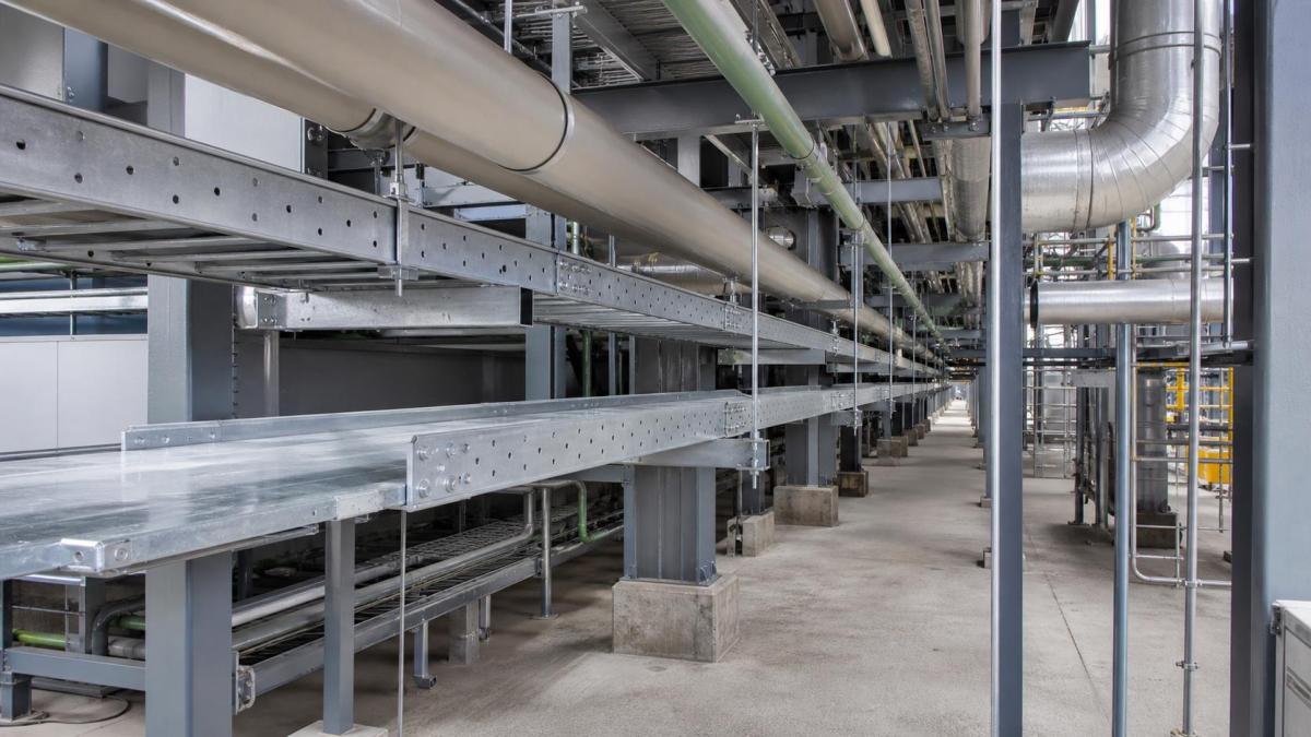
Cable tray routes rarely occupy an industrial building alone. They share ceiling zones, equipment rooms, pipe corridors, access platforms, ventilation spaces, and structural steel with other services. A route that looks clear on an electrical plan can become difficult to install when a large pipe, duct, valve, beam, or maintenance walkway is added to the coordinated model.
For EPC contractors and MEP installers, cable tray coordination is a procurement issue as well as a drawing issue. The supplier needs enough information to provide practical bends, reducers, supports, covers, and strut channel. Early coordination also reduces field cutting and helps keep the cable management system accessible after commissioning.
Reserve a Three-Dimensional Route
A cable tray schedule should be linked to a three-dimensional route reservation. The reservation should show tray width and side height, cover allowance, cable pulling space, support steel, and access clearance. It should also identify the direction of cable entry at panels, motors, transformers, junction boxes, and packaged equipment.
Elevation is as important as plan position. Two tray routes may fit on a plan but collide when one route changes level near a pump, a process skid, or a structural beam. The coordinated drawing should show straight lengths, horizontal and vertical fittings, reducer locations, and the space needed to install splice plates and cable cleats.
Review the Main Conflict Zones
Several locations deserve a focused coordination review before fabrication:
- Pipe and duct crossings: keep cable routes away from hot surfaces, condensate discharge, drain paths, and removable insulation where the project design requires separation.
- Equipment interfaces: leave room for cable glands, termination boxes, doors, removable panels, and vendor-supplied connection points.
- Structural members: confirm whether brackets can be fixed to concrete, steel beams, or a dedicated support frame without weakening the structure.
- Access and maintenance areas: do not place a tray, cover, or support across a walkway, lifting path, valve operating area, or removable equipment zone.
- Penetrations: coordinate sleeves, fire-rated barriers, waterproofing, and the final tray approach before the opening is formed.
When a conflict cannot be avoided, the design should define the adjustment. A controlled offset with two bends is usually easier to fabricate and inspect than an unplanned field modification at the edge of a pipe rack.
Choose a Tray Form That Supports Coordination
Cable ladder is often practical for heavy power routes where cables need ventilation and clear fixing points. Perforated cable tray offers continuous support for control and smaller power cables and can be easier to cover near equipment. Wire mesh cable tray can help in light data or instrumentation routes with frequent branch changes. Cable trunking is useful when enclosed protection and a clean interface with panels are required.
The choice affects the fitting schedule. A covered perforated tray needs compatible cover clips and fitting covers. A ladder route may need dedicated cable cleats at bends and risers. A wire mesh route may use different connectors and support brackets. These differences should be reflected in the coordinated model and the bill of quantities.
Coordinate Supports With Structure
Supports are part of the route, not an afterthought below it. A cantilever arm may be suitable along a concrete wall, while a trapeze frame may be more efficient in an open ceiling. Structural steel may require clamps, welded attachments, or a separate support frame subject to the project's approval process.
The support layout should account for tray loading, fitting locations, concentrated cable loads, covers, and future additions. Brackets should not block pipe access or interfere with insulation. Where several tiers share a support, the vertical gap should permit cable installation, inspection, and later removal of the upper tray without damaging the lower route.
Strut channel, threaded rods, anchors, brackets, splice plates, and fasteners should be listed with the tray system unless another package clearly owns them. Splitting responsibility without an interface schedule is a common cause of missing site hardware.
Plan for Heat, Water, and Fire Interfaces
Nearby services can change the environmental condition around a cable route. Hot process lines may affect cable selection and separation. Chilled-water pipes may create condensation. Outdoor or washdown areas may require covers, drainage consideration, and a corrosion-resistant finish. The material and surface treatment should follow the actual exposure rather than the building label alone.
Where a tray crosses a fire-rated wall or floor, the opening, tray approach, support position, and approved fire-stop system should be coordinated as one detail. The tray should not rely on the fire-stop material for support. Waterproofing and fire requirements may also conflict at below-grade or wet-area penetrations, so the responsible design disciplines should confirm the approved construction.
Make the RFQ Coordination-Ready
A supplier can quote more accurately when the inquiry includes the coordination information that affects fittings and supports:
- Coordinated plan and elevation drawings with route tags and equipment interfaces
- Tray type, clear width, side height, thickness, material, finish, and cover requirement
- Cable quantity, outside diameter, weight, segregation rules, and future capacity
- Pipe, duct, structural, walkway, fire barrier, and waterproofing constraints
- Bends, tees, crosses, reducers, offsets, risers, drop-outs, and special lengths
- Support type, fixing surface, loading condition, bracket spacing, and shared-tier details
- Splice plates, fasteners, bonding parts, dividers, cover clips, and packing sequence
- Project drawing format, inspection documents, delivery zones, and installation stages
Work With Hongfeng Electric
Hongfeng Electric can review coordinated cable tray layouts for industrial EPC and MEP projects, including cable ladder, perforated tray, wire mesh tray, cable trunking, strut channel, supports, fittings, covers, and bonding accessories. Send the latest coordinated drawings, route schedule, cable data, structural constraints, and delivery plan with your RFQ. This gives the quotation a defined installation scope and helps reduce missing fittings during site work.
Navigation
Send Us A Message
Get in touch with us
Phone