
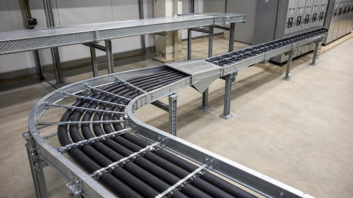
Large power cables do not follow a cable tray route as freely as small control wires. Their minimum bending radius, pulling tension, sidewall pressure, cleat spacing, and termination geometry can determine the tray width and fitting radius. When these points are left until installation, contractors may face field-cut fittings, overcrowded bends, damaged cables, or routes that cannot enter switchgear as designed. Early coordination between the cable schedule, tray layout, and fitting bill of quantities prevents many of these problems.
Start With Cable Data, Not a Standard Bend
The cable manufacturer's data should define the minimum bending radius for each cable type and condition. Requirements may differ between a cable under pulling tension and the same cable in its final installed position. Conductor size, insulation system, armor, shielding, overall diameter, and cable construction all affect the permitted radius.
A tray fitting radius must give the installed cable enough space to follow the required curve. The nominal radius of a bend is not always the same as the usable cable path inside the fitting. Side rails, rungs, splice plates, reducers, covers, and nearby cables can reduce available space. EPC buyers should therefore provide the largest cable outside diameter and required bending radius instead of ordering bends only by tray width and angle.
Choosing Tray Type for Large Power Cables
Cable ladder is widely used for heavy power feeders because it offers ventilation, strong side rails, and convenient cable cleating. Rung spacing should support the cable without excessive sag and should allow cleats to be fixed at the required intervals. Perforated cable tray can provide continuous support for smaller power and control cables, but weight and heat dissipation still need checking.
- Cable ladder: suited to heavy feeders, large diameters, and routes needing cable cleats.
- Perforated cable tray: suitable for medium and smaller cables where continuous support is useful.
- Cable trunking: provides enclosed protection but requires careful review of cable fill, heat, and entry geometry.
- Wire mesh cable tray: generally better suited to lightweight power, control, and data services than large heavy feeders.
Tray loading should include cable weight over the selected support span. At vertical runs or steep inclines, the support system must account for cable weight transfer and the cleat arrangement. The tray itself should not be used as the only cable restraint unless the system is designed for that function.
Horizontal Bends, Vertical Bends, and Risers
Horizontal bends change route direction in plan. Inside and outside vertical bends change elevation, while risers transition between horizontal and vertical routes. Each fitting should use a radius compatible with the cable data. A sharp 90-degree corner assembled from short straight pieces may fit the building geometry but still be unsuitable for the cable.
Vertical transitions need particular attention near transformers, switchgear, motor control centers, generators, and large motors. The final cable entry point, gland plate orientation, termination height, and required straight length before the gland influence the tray approach. A coordinated elevation or 3D model is more useful than a plan view alone.
Tees, Crosses, and Cable Branching
Tees and crosses are not simply junction boxes for power cables. The branch arrangement must allow cables to separate without crossing tightly or blocking other circuits. Cable pulling direction should be considered, especially where several feeders leave a main ladder route. In some cases, two staggered tees provide better cable paths than one compact cross.
Reducers should be positioned after cable groups divide, not where they compress the main bundle before a branch. Offset reducers can keep one side aligned with a wall or equipment row, while symmetrical reducers maintain the tray centerline. The bill of quantities should distinguish these types because they are not interchangeable on a coordinated route.
Pulling Loads and Temporary Installation Forces
The cable tray's normal operating load is not the only force present during installation. Pulling rollers, sheaves, temporary supports, and pulling equipment can impose local loads at bends and route changes. The installation method should prevent rollers from damaging rung edges or applying unverified concentrated loads to the tray.
Pulling calculations are normally prepared by the cable installation team. They may include maximum pulling tension and sidewall pressure at bends. Those calculations should inform bend radii, pulling direction, intermediate pulling points, and access space. A route that meets the final bending radius can still be difficult to install if the pulling sequence has not been considered.
Cable Cleats, Spacing, and Short-Circuit Forces
Power cable cleats restrain cables under normal conditions and, where specified, during short-circuit forces. Cleat type and spacing depend on cable arrangement, fault level, cable diameter, and manufacturer data. The cable ladder rung or support member must be capable of receiving the cleat loads.
At bends, cleat locations should hold the cable in the intended path without forcing it below the minimum radius. Additional cleats may be required near vertical transitions, terminations, and route changes. Buyers should include cleats, fixing hardware, and any special rung requirements in the RFQ if they are part of the supply package.
Covers, Dividers, and Fill Allowance
Covers may be required for outdoor exposure, falling objects, sunlight, or process contamination. A cover must have adequate clearance above the highest cable and cleat. Hold-down clamps should suit wind and vibration conditions. At large-radius fittings, matching bend covers and fasteners should be listed separately.
Dividers can separate cable groups, but they also consume internal width and can restrict the usable bend path. Future cable allowance should be planned as physical space, not only as a percentage in a spreadsheet. The arrangement should remain workable through bends, tees, and equipment entries, where congestion is usually greater than on straight tray lengths.
Support and Splice Locations Around Fittings
Bends, tees, crosses, reducers, and risers may need additional supports according to the tray manufacturer's guidance and project standard. A fitting should not be left cantilevered from a distant straight-section support. Splice joints should be placed where they can be assembled and inspected, with the correct splice plates and fasteners.
Expansion connectors are needed on long routes where thermal movement exceeds the capacity of standard joints. Bonding jumpers may be required across expansion fittings or joints that do not provide the specified electrical continuity. These items belong in the fitting and accessory schedule, not as a site afterthought.
RFQ Checklist for Power Cable Tray Fittings
- Cable type, quantity, outside diameter, weight, and minimum bending radius
- Tray type, width, side height, rung spacing, material, and finish
- Distributed load, support spacing, and future cable allowance
- Horizontal and vertical bend angles and required fitting radii
- Tees, crosses, offset or symmetrical reducers, and riser details
- Equipment entry elevations, termination orientation, and required straight lengths
- Cable cleat type, spacing, fixing hardware, and short-circuit criteria
- Covers, dividers, splice plates, expansion fittings, and bonding jumpers
- Layout drawings, fitting schedule, installation sequence, and packing labels
Work With Hongfeng Electric
Hongfeng Electric can manufacture cable ladder, perforated cable tray, cable trunking, large-radius bends, tees, reducers, risers, covers, splice plates, and support accessories for project-specific routes. For an accurate quotation, send the tray layout, cable schedule, minimum bend radii, load and support data, fitting list, material finish, and equipment entry details. HF Cable Tray can use this information to check the supply scope and prepare coordinated items for installation.
Navigation
Send Us A Message
Get in touch with us
Phone