
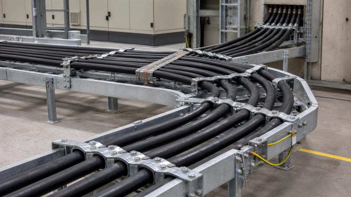
Large power cables installed on a cable tray can experience significant mechanical forces during a short-circuit event. The tray provides a route, but it does not automatically restrain every cable in the required position. Cable cleats, clamps, support points, tray construction, and the arrangement through bends must be selected as a coordinated system.
For electrical contractors and project buyers, the important question is not simply how many cleats to order. The project must define the cable arrangement, fault duty, installation environment, fixing surface, and required restraint behavior. Those inputs allow the supplier and responsible electrical designer to develop a suitable cable support package without relying on a generic accessory list.
Start With the Cable and Fault Data
Cable cleat selection should begin with the actual cables. The inquiry should identify conductor size, outside diameter, single-core or multi-core construction, cable weight, installation orientation, bending radius, and the number of circuits sharing the route. The responsible electrical design team should also provide the short-circuit duty and the project criteria used to assess mechanical restraint.
Fault forces can vary with conductor arrangement and the distance between restraint points. A cleat suitable for a small multi-core cable should not be assumed to suit closely spaced single-core power cables. Cable spacing, phase arrangement, and the position of parallel circuits can affect how the forces are transferred to the cleat and tray.
Match Cleats to the Cable Arrangement
Different cable arrangements call for different restraint approaches:
- Single-core power cables: select cleats that hold the intended phase arrangement while maintaining the required cable spacing and avoiding unnecessary pressure on the sheath.
- Multi-core power cables: review the cable diameter, weight, and bending behavior so the cleat holds the cable without damaging its outer layer.
- Parallel circuits: confirm whether each circuit needs separate restraint and how the groups are arranged at bends, risers, and equipment entries.
- Vertical routes: use a dedicated weight-support strategy so the cable cleat and tray are not asked to carry an undefined cable drop.
Material compatibility also matters. Cleats and fasteners should be suitable for the cable sheath, tray material, moisture exposure, temperature, and project finish requirements. In outdoor or corrosive areas, the cleat material and hardware should be reviewed together with the tray coating and bonding parts.
Check the Tray and Support Structure
A cleat is fixed to something. The tray rung, perforated base, side rail, support arm, or dedicated channel must be able to accept the fixing method and transfer the restraint forces. The supplier's loading information and the project's support design should be reviewed at the same time.
Cable ladder is often selected for heavy power routes because the rungs provide accessible fixing locations. A perforated tray may be suitable where continuous support is needed, but the cleat fixing detail must be compatible with the tray profile and hole pattern. Cable trunking may use internal cleats or clamps, while wire mesh tray is generally evaluated for lighter routes and different fastening hardware.
Supports near bends and equipment entries deserve special review. Restraint forces can be transferred into the tray fitting and its support, not just the straight section. A fitting with insufficient support may move even when the cleat itself is correctly selected.
Coordinate Bends, Risers, and Terminations
Cables need to maintain their minimum bending radius through horizontal bends, vertical bends, tees, reducers, and risers. Cleats placed too close to a bend can force the cable into a tight path. Cleats placed too far away may leave the cable unsupported where movement is most likely.
At equipment entries, the restraint detail should coordinate with gland plates, cable boots, termination boxes, and removable covers. The cable should be supported before the termination so that the gland or terminal does not carry the route load. Where cables enter from below or rise vertically, the drawing should distinguish weight support from short-circuit restraint.
Parallel cables also need a consistent phase and circuit arrangement along the route. A route that changes grouping at a bend can create installation confusion and may affect the design assumptions. Route tags and cable markers should match the approved installation drawing.
Review Bonding and Corrosion Details
Metallic cleats, tray sections, support steel, and bonding conductors may form part of the project's protective bonding arrangement. The electrical designer should define which components require continuity and where dedicated bonding connections are installed. The cleat itself should not be treated as a substitute for the specified tray bonding system.
In humid, coastal, chemical, or outdoor environments, dissimilar metal contact can accelerate corrosion. Buyers should confirm cleat material, fastener material, isolating components where required, surface finish, and compatibility with the tray system. Field-drilled holes and cut edges should follow the project's approved corrosion protection method.
Build a Complete Cleat RFQ
An accessory request that states only cable size and quantity is difficult to verify. Include the following information in the package:
- Cable type, outside diameter, weight, single-core or multi-core construction, and bend radius
- Phase and circuit arrangement, parallel circuits, route orientation, and cable grouping
- Short-circuit duty and electrical design criteria for the restraint assessment
- Tray type, width, side height, rung or base construction, material, and surface finish
- Cleat spacing or design requirement, fixing method, support spacing, and anchor details
- Bends, tees, reducers, risers, equipment entries, gland plates, and termination constraints
- Bonding, corrosion, temperature, moisture, fire, and outdoor exposure requirements
- Cleat drawings, product data, inspection documents, packing labels, and delivery stages
Work With Hongfeng Electric
Hongfeng Electric can help project buyers coordinate cable ladder, perforated cable tray, supports, cable cleats, fittings, covers, strut channel, and bonding accessories for heavy power routes. Send the cable schedule, route drawings, fault-duty criteria, tray details, environmental conditions, and equipment entry drawings with your RFQ. This allows the quotation to address both the cable support route and the mechanical restraint accessories required for installation.
Navigation
Send Us A Message
Get in touch with us
Phone