
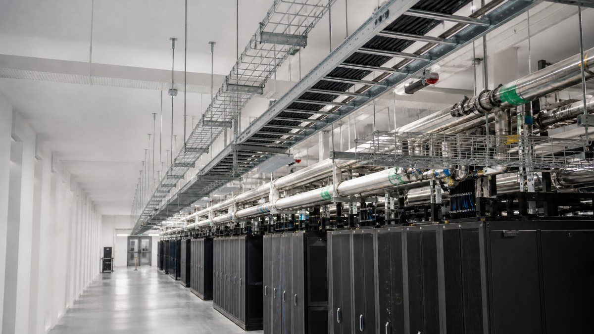
AI data centers are changing the coordination problem above and around the rack. Higher-density computing can bring larger power feeds, more network connections, coolant distribution units, facility-water interfaces, leak detection, and tighter equipment keep-out zones into the same room. Cable tray is still a familiar product, but the assumptions used for a conventional enterprise data hall may no longer produce an installable route.
The important shift is not a single tray type or a universal layout. It is the need to coordinate electrical distribution, fiber pathways, liquid-cooling pipes, structural support, fire protection, and rack replacement as one system. Owners, consultants, contractors, and suppliers should freeze interfaces early enough for procurement while preserving flexibility for equipment that may change before installation.
Why the Traditional Overhead Zone Is Under Pressure
A conventional layout may reserve separate overhead levels for power, communications, containment, and building services. An AI hall can add supply and return coolant piping, manifolds, rack-side or in-row coolant distribution equipment, drip management, leak sensors, and service access. Busway, cable tray, and fiber basket may also need more drops or more frequent changes as rack power architecture evolves.
This makes elevation as important as plan position. A route that appears clear on a reflected ceiling plan may block a valve, prevent removal of a manifold, conflict with a busway tap-off, or leave no safe path for a future cable bundle. Structural loads can also accumulate when several systems share a narrow ceiling corridor. Tray support design therefore needs verified loads and coordinated attachment points, not only standard spacing copied from an earlier project.
The rack layout is another moving interface. Some projects keep power conversion and backup components inside or beside the rack; others place more equipment at row or room level. New low-voltage DC concepts are also being developed for future high-density facilities, but they are not a universal replacement for current architectures. Cable tray procurement must follow the approved project design and avoid assuming that every AI hall uses the same voltage, busway, or cable arrangement.
What Changes for Power Cable Tray
Ladder cable tray remains a practical option for many fixed power-feeder routes because it provides ventilation, mechanical support, and accessible cable entry. Higher load concentration can require deeper side rails, stronger profiles, shorter support spans, or additional tiers. The correct response depends on actual cable type, quantity, weight, grouping, route length, support geometry, and the approved distribution architecture.
Rack drops deserve more attention than straight runs. Repeated vertical transitions can create concentrated cable loads and crowd the rack service zone. Large-radius bends, drop-out fittings, edge protection, and local supports should be included in the bill of materials. If the design uses busway for primary rack distribution, cable tray may still carry control power, auxiliary feeds, monitoring circuits, and connections to cooling equipment.
Spare capacity should be route-specific. Leaving physical room for future cables is useful only if bends, supports, rack entries, and upstream electrical capacity can support the addition. A wide empty tray that blocks coolant service access is not meaningful flexibility. Teams should define likely expansion scenarios and reserve space where those scenarios can actually be delivered.
Liquid Cooling Creates New Interface Rules
Liquid-cooling systems introduce pipes, hoses, manifolds, valves, heat exchangers, and coolant distribution units into the technology space. Cable tray should occupy a clearly defined zone with enough separation for installation, inspection, leak detection, and maintenance. Pipes should not be supported from cable tray, and tray should not be used as an informal platform for hoses or sensors.
The route should consider credible leak and condensation paths without claiming that one fixed separation solves every project. Equipment arrangement, fluid type, pressure, joint locations, drip management, and owner requirements all matter. Electrical and mechanical designers should agree on crossings, vertical order, service clearances, and emergency access before supports are released for fabrication.
Coolant distribution units also need power, controls, alarms, and communication links. These local branches should be visible in the cable schedule, not discovered after the main tray has been installed. Removable equipment should retain a practical disconnection and replacement path. Tray supports, pipe supports, and rack frames may be close together, but their structural responsibilities should remain clear.
Fiber Pathways and Monitoring Need Their Own Space
AI clusters can create dense east-west network connections as well as links to storage, management, and facility systems. Wire-mesh basket or another approved pathway may be used for fiber and low-voltage communications, but it should not become the overflow route for every small cable. Bend control, pathway loading, rack entry, cable identification, and access for moves and changes should be agreed with the network design.
Monitoring also expands beyond traditional environmental sensors. Cooling controls, leak detection, valve status, power metering, rack management, and security systems can add many small branches. Their physical route may appear minor in the model, yet branch fittings and drops can crowd the same area needed for fiber and coolant service. A dedicated pathway schedule helps the contractor avoid mixing services during installation.
Procurement should distinguish heavy-duty ladder tray, perforated tray, and wire-mesh basket rather than grouping them under one cable-support quantity. Each system needs compatible bends, couplers, dividers, supports, drop-outs, edge protection, and finish. Where pathways cross, the coordinated detail should preserve cable bend requirements and maintenance clearance without creating unsupported field bridges.
Conventional Hall Assumptions vs AI-Ready Coordination
| Coordination Item | Common Earlier Assumption | AI-Ready Review |
|---|---|---|
| Overhead space | Power and fiber occupy predictable levels. | Coordinate busway, power tray, fiber basket, coolant pipes, manifolds, leak systems, and service keep-outs in three dimensions. |
| Rack drops | Standard repeated drops fit most rows. | Verify each rack or sidecar interface, cable load, bend path, coolant connection, and replacement access. |
| Support loads | Tray load controls the support selection. | Assess tray, cables, fiber, containment, nearby cooling services, maintenance loads, and shared structural attachments separately. |
| Future capacity | Apply one spare percentage to all routes. | Reserve usable capacity tied to realistic rack, power, cooling, and network expansion scenarios. |
Six Actions before Releasing the Tray Package
- Freeze rack, busway, tray, fiber, coolant manifold, and CDU interface elevations on coordinated sections.
- Issue cable loads and support spans by route rather than selecting tray from width alone.
- Define separate pathways and crossings for power, fiber, controls, leak detection, and cooling services.
- Include bends, drop-outs, reducers, splice hardware, barriers, supports, and rack-interface accessories in the RFQ.
- Check maintenance access for valves, manifolds, tap-off units, containment panels, sensors, and removable racks.
- Review realistic expansion states so spare tray space remains physically usable after cooling and power changes.
The release package should include coordinated sections, route schedules, typical rack drops, load criteria, support responsibilities, and a clear list of provisional interfaces. If rack or cooling equipment changes after purchase, the project should assess the effect on tray width, drop location, support load, access, and fitting quantity before approving the change. This is more reliable than absorbing every late revision through field cutting.
Final Engineering and Buying Advice
AI infrastructure does not make conventional cable tray obsolete. It makes coordination quality more visible. Buyers should compare suppliers on verified load performance, dimensional consistency, complete fittings, support compatibility, finish quality, labeling, documentation, and the ability to manufacture repeatable rack drops. Straight tray price alone does not capture the cost of a crowded overhead zone.
HONGFENG / Cable Tray Pro can review route schedules, fitting quantities, support interfaces, and export packing requirements for high-density data center projects. Final cable tray selection, service separation, structural support, liquid-cooling coordination, and installation must follow the approved project design, equipment requirements, and applicable local rules.
Navigation
Send Us A Message
Get in touch with us
Phone