
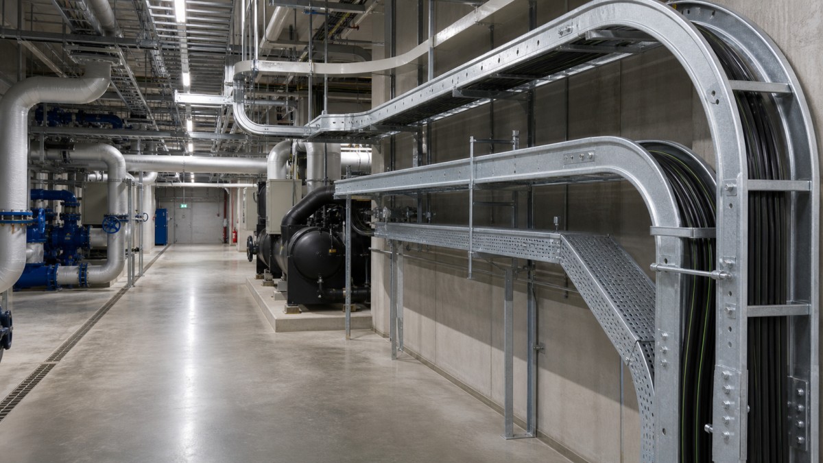
District cooling and central utility plants concentrate large electrical loads in a compact operating facility. Chillers, primary and secondary pumps, condenser-water pumps, cooling towers, water-treatment equipment, variable-frequency drives, switchgear, controls, and metering systems all depend on organized cable routes. The plant may also be built in phases, requiring the first installation to serve current equipment without blocking future modules.
Cable tray procurement in these projects must balance heavy motor feeders, dense control wiring, humid or wet areas, limited ceiling space, equipment-removal routes, and continuous maintenance access. Buying tray only by width and total length can leave major gaps in fittings, support steel, covers, cable-drop accessories, and material compatibility. A route-based specification gives engineers, contractors, and suppliers a more dependable basis.
Map the Main Cable Tray Environments
The chiller hall usually combines large equipment footprints with overhead chilled-water and condenser-water piping. Motor feeder routes need direct access to chillers and pumps while remaining clear of lifting beams, tube-pull zones, valves, and service platforms. The cooling-tower and heat-rejection areas are typically more exposed to moisture and outdoor weather. Water-treatment rooms may introduce chemical exposure, washdown, and frequent maintenance activity.
Electrical rooms have a different problem: high cable density and many entries into switchboards, motor-control centers, and drive panels. Control rooms and network spaces use smaller cables but require organized separation and accessible branch routes. Utility tunnels, trenches, rooftop routes, and energy-transfer stations can add long runs outside the central plant.
The tray schedule should identify each zone and route service. At minimum, it should record tray type, internal dimensions, side-rail height, material and finish, cable load, support concept, cover requirement, fitting quantity, and planned spare capacity. This prevents a dry electrical-room specification from being applied automatically to cooling-tower or water-treatment routes.
Select Tray Type by Cable Group and Access Need
Ladder Tray for Chiller and Pump Feeders
Ladder cable tray is widely considered for large motor and main distribution feeders because it provides strong side rails, open ventilation, and practical cable access. In a central utility plant, the actual design must account for cable size and weight, number of circuits, cable grouping, support span, changes in elevation, and concentrated loading near vertical drops.
Perforated Tray for Controls and Building Services
Perforated tray offers more continuous support for control, instrumentation, metering, communication, and smaller auxiliary cables. It can occupy a separate tier on a common support frame, provided that required separation and access are maintained through bends and branches. Buyers should specify the perforation pattern, divider needs, cover arrangement, and compatible drop-out accessories.
Trunking for Protected Local Routes
Cable trunking can suit selected control-panel branches, energy-metering routes, and public or accessible plant areas where additional enclosure is useful. In humid service, enclosed routes need deliberate drainage and condensation management. Covers and internal dividers should remain removable without dismantling nearby pipework.
Control Moisture and Corrosion as a System
Cooling plants are not uniformly dry. Condensation can occur around chilled surfaces, and cooling-tower or water-treatment zones may expose equipment to persistent moisture. Plant location also matters: a coastal installation can face a different corrosion environment from an inland basement plant. The approved material and finish should be selected for the actual area, expected service life, maintenance practice, and owner requirements.
| Plant Zone | Typical Route Duty | Key Selection Check |
|---|---|---|
| Electrical and drive rooms | Dense feeder and control entries in a controlled indoor area | Confirm cable separation, panel approach, support capacity, and future entry space. |
| Chiller and pump halls | Large motor feeders plus control and monitoring circuits | Coordinate load, bends, equipment-removal zones, pipe clearances, and cable drops. |
| Cooling towers and outdoor utilities | Weather-exposed power and control distribution | Verify corrosion protection, drainage, cover need, compatible supports, and fasteners. |
| Water-treatment and wet service | Smaller equipment circuits in humid or chemically exposed areas | Review complete material system, washdown exposure, drainage, and maintenance access. |
Hot-dip galvanized steel may offer a practical option for many plant and outdoor routes when it meets the project corrosion requirements. Pre-galvanized steel may be considered in approved dry indoor areas. Stainless steel or another specified system can be more appropriate for aggressive wet, coastal, or chemical environments. The tray, fittings, brackets, bolts, washers, splice plates, cover clamps, and bonding parts should use compatible materials.
Covers should be assigned by route rather than applied everywhere. They can reduce exposure to dripping water or falling material, but they can also limit cable access and affect heat dissipation. Outdoor covers need secure fasteners, while enclosed or perforated routes need drainage details that do not direct water toward equipment entries.
Coordinate Motor Feeders, Drives, and Control Routes
Large chillers and pumps can create substantial feeder groups. Cable arrangement should follow the electrical design, cable manufacturer's requirements, and equipment vendor instructions. When variable-frequency drives are used, route planning may need specific attention to cable type, bonding, separation, and the relationship between drive output cables and sensitive control or communication circuits. These requirements should be resolved before tray tiers and barriers are released for manufacture.
Separate tray tiers can make cable services easier to inspect and expand. However, separation must continue at crossings, vertical risers, panel drops, and equipment branches. A common support frame should still allow technicians to remove a cover or install a cable without disturbing another service. Tray elevation should also provide a controlled cable bend into motors, local isolators, sensors, and control panels.
Bonding continuity and grounding accessories need to match the approved electrical design. Painted surfaces, expansion connections, removable sections, and transitions between tray systems may require specific details. Procurement documents should state which bonding parts are part of the tray supplier's scope and which are installed under the electrical contract.
Protect Maintenance Space and Future Plant Capacity
A district cooling plant is maintained throughout its operating life. Chiller tubes, compressors, motors, pumps, valves, strainers, and heat exchangers all need removal or service space. Cable tray should stay outside those zones and should not prevent operation of lifting equipment. Supports fixed to removable panels, equipment bases, or unverified pipe supports can create avoidable shutdown work later.
Phased plants need a clear expansion strategy. Future chillers or pumps may justify reserved tray tiers, support arms, or corridor width. The design should distinguish true future circuits from a general allowance. Supports and main routes can then be prepared for likely additions, while unnecessary tray width is avoided in fixed local branches.
Constructability reviews should include cable pulling as well as equipment access. Long feeder cables require practical bend radii, pulling direction, roller positions, and entry space. Large-radius bends and reducers should be included in the bill of materials, and fittings should receive adequate support. This is especially important where routes turn around pipes or descend to equipment in a crowded hall.
District Cooling Cable Tray RFQ Checklist
- List tray quantities by chiller hall, pump area, electrical room, cooling tower, water treatment, and external route.
- Define tray type, dimensions, load, support span, material, finish, covers, and spare capacity.
- Coordinate large motor feeder routes with drive, cable, and equipment manufacturer requirements.
- Maintain approved separation for power, control, instrumentation, communication, and other designated services.
- Include bends, tees, reducers, risers, drop-outs, barriers, covers, splice parts, hold-down clamps, and supports.
- Check corrosion compatibility of the complete tray and support assembly in wet or outdoor zones.
- Preserve chiller, pump, valve, and lifting-equipment maintenance clearances.
- Request dimensional drawings, load information, finish records, accessory lists, and packing identification.
Final Buying Advice
The best cable tray package for a district cooling plant supports both the electrical design and the operating plant. Buyers should evaluate load performance, fitting completeness, corrosion compatibility, support coordination, maintenance access, and future expansion together. A complete route schedule and accessory bill of materials make supplier comparisons more accurate than a simple price per meter.
HONGFENG / Cable Tray Pro can review tray schedules, route conditions, material choices, fittings, and international packing requirements for central utility projects. Final support design, cable arrangement, and installation must follow the approved engineering documents, equipment instructions, and applicable local requirements.
Navigation
Send Us A Message
Get in touch with us
Phone